Scheme 1.
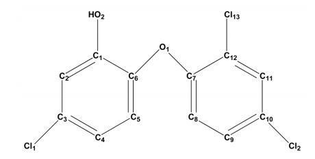
Structure of TCS

As a kind of multi-purpose biocide, triclosan (TCS) was widely used in many daily chemical products such as soap, toothpaste and detergent[1-3]. The waste of these products will be constantly discharged into environment. TCS may probably degrade into the harmful chlorphenol and dioxin species, which will pollute water body and even influence the ecotype and human health[4]. Therefore, it is of great importance to develop a new reliable and simple method for TCS detection with high selectivity and sensitivity.
During the past decades molecular imprinting technique has developed rapidly, which is a useful approach for the recognition and isolation of target molecules[5-7]. Molecularly imprinted polymers (MIPs) are assembled around a suitable template molecule or structure. Removal of the template will form microcavities with a specific size, shape and chemical functionality in the cross-linked host[8-10]. Recently, molecularly imprinted electrochemical sensors have attracted more and more attention since they possess much superiority such as unique electrical properties, cost effectiveness, low detection limit and easy miniaturization[11-14]. Especially, the nanosensors based on MIPs have proposed for promising applications like graphene, carbon nitride nanotubes and carbon nanotubes[15-19].
Recently, computational approaches have been used to screen functional monomers and calculate the interaction energies between template and functional monomers in order to achieve high selectivity and rebinding capacity to the template[20-22]. Using computational approaches in MIPs design provides many advantages: low costs, time saving and environmental safety as no disposal of chemicals is needed[23-26]. The application of computational approaches in MIPs has steadily increased, demonstrating the potential of molecular modeling towards rational MIPs design[27-29].
There is no report about the detection of TCS by using molecular imprinting technique combined with computational simulation. Mehmet et al. reported a molecularimprinted electrochemical sensor based on gold nanoparticles decorating polyoxometalate/reduced graphene oxide for the determination of TCS in waste water[30]. A very recently published report demonstrated electrochemical sensor based on molecularly imprinted polymer for sensitive TCS detection in wastewater and mineral water[31]. In this study, the template-monomer complexes formed by single kind of monomers or hybrid monomers were computational simulated, and the result showed that the complex formed by hybrid monomers (TCS(o-phenylenediamine-co-resorcinol)) has more hydrogen bonds and larger binding energy than that by single kind of monomers (TCS(o-phenylenediamine)2 and TCS(resorcinol)2). Based on the computational simulation results, o-phenylenediamine and resorcinol were used as imprinting monomers, and then a voltammetric sensor for detection of TCS was synthesized using molecularly imprinted poly(o-phenylenediamine-co-resorcinol). The imprinted copolymer exhibits a high sensitivity and selectivity for TCS sensing.
All the reagents in the experiments were of analytical grade and used as received without any further purification. Triclosan (TCS), 2, 4, 6-trichlorophenol (TCP), 4-chloro-3, 5-dimethylphenol (PCMX), resorcinol and o-phenylenediamine were obtained from Aladdin Chemicals. Boric acid, phosphoric acid, acetic acid, sodium hydroxide and absolute ethyl alcohol were purchased from Beijing Chemical Factory. Ultrapure water with resistivity 18 MΩ⋅cm-1 was used throughout.
Electrochemical experiments were carried out in a three-electrode system with a CHI 660D electrochemical workstation (CH Instruments, Chenhua Co., Shanghai, China) with a bare or MIPs glassy carbon (GC) electrode (3 mm in diameter) as working electrode, platinum sheet as auxiliary electrode and Hg/Hg2Cl2 electrode (SCE) as reference electrode. GC electrode was successively polished on a microcloth (chamois leather) with 0.3 and 0.05 µm aqueous slurry of alumina, and washed with water and alcohol alternately. Galvanometry used cyclic voltammetry (CV) and differential pulse voltammetry (DPV) methods in a 5 mM potassium ferricyanide aqueous solution (containing 0.2 M KCl). DPV voltage ranged from –0.2 to 0.6 V, step potential was 4 mV and amplitude was 50 mV. All electrochemical experiments were carried out at room temperature.
Imprinted film was modified on a GC electrode by cyclic voltammetry in 50 mL aqueous solution containing 0.10 mM TCS and hybrid monomers (5 mM resorcinol and 5 mM o-phenylenediamine) in Britton-Robinson buffer solution with pH 5.0 (marked MIPs/GC). The cycling potential range was between 0 and 0.8 V with a scan rate of 50 mV⋅s-1 and the electrodeposition was finished after 20 cycles. Then the imprinted electrode was immersed into 0.1 M NaOH aqueous solution for 40 min in order to exclude TCS molecules from the imprinted electrode. As a control electrode, the corresponding non-imprinted electrode (NIPs/GC) was prepared with the same procedure described above but without adding TCS.
We used density functional theory (DFT) to optimize TCS molecule (Scheme 1) at the CAM-B3LYP/6-31G(d, p) level. The optimized and experimental data[32] of TCS are shown in Table 1, from which we can conclude that the CAM-B3LYP method was reliable. Therefore, the CAM-B3LYP/6-31G(d, p) method was proved to be the reasonable method for geometry optimization. Thus, we used the CAM-B3LYP/6-31G(d, p) method for all the geometry optimizations in the rest of this study.
 DownLoad:
CSV
DownLoad:
CSV
| CAM-B3LYP/6-31G(d, p) | Exp.a | Δ | |
| R (Ǻ) | |||
| C1–O2 | 1.37273 | 1.35301 | 0.01972 |
| C3–Cl1 | 1.74044 | 1.74556 | 0.00512 |
| C6–O1 | 1.39642 | 1.37631 | 0.02011 |
| C7–O1 | 1.37885 | 1.36410 | 0.01475 |
| C12–Cl3 C10–Cl12 |
1.72847 1.74062 |
1.73707 1.74612 |
0.00860 0.00550 |
| Φ (°) | |||
| O2–C1–C6 | 117.95046 | 117.24838 | 0.70208 |
| O2–C1–C2 | 122.51881 | 123.46024 | 0.94143 |
| C2–C3–Cl1 | 118.42176 | 118.74993 | 0.32817 |
| C4–C3–Cl1 | 119.44432 | 119.67298 | 0.22866 |
| O1–C6–C5 | 119.71959 | 119.42554 | 0.29405 |
| O1–C7–C8 | 124.54448 | 123.89221 | 0.65227 |
| C7–C12–Cl3 | 119.88970 | 119.79042 | 0.09928 |
| C11–C12–Cl3 | 118.71799 | 119.52212 | 0.60839 |
| C11–C10–Cl2 | 118.09670 | 119.32638 | 1.22968 |
| C9–C10–Cl2 | 120.64145 | 119.87432 | 0.76713 |
| a Ref. [32]. | |||
The model of the template-monomer complexes was set up so as to understand the template-monomer interactions at the molecular level. Then all calculations had been completed using the Gaussian 09 software[33] with the Linux operating system. Electronic energies were calculated at the CAM-B3LYP level with the 6-31G(d, p) basis set. In this work, single kind of monomers and hybrid monomers were selected to compare their complex stability with TCS in gas phase. The electronic stabilization energy, ΔE, was calculated by the equation as follows:
|
|
where "n" refers to the number of monomers in the templatemonomer complex. Charge distribution was investigated by the Millikan charge.
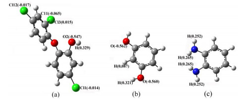
The optimized structure of TCS template, resorcinol and o-phenylenediamine monomers are shown in Fig. 1, in which the Millikan charges of the possible proton acceptors and donors are signed out. In TCS template molecule, Cl3 atom has the positive Millikan charge (0.015), so it cannot form hydrogen bonds with the H atoms in resorcinol or o-phenylenediamine monomers. It can be seen from the optimized conformations that there are both proton acceptors and donors in TCS and the monomers. The C and O atoms with negative Millikan charges can act as proton acceptors and the H atoms with positive Millikan charges as donors. Thus, hydrogen bonds will possibly form between the proton acceptors and donors.
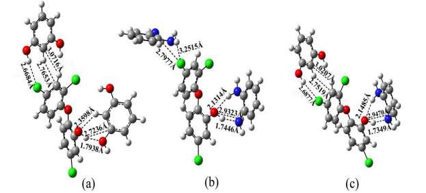
Based on the research of the above Millikan charges, we simulated the complexes formed by TCS template and single kind of monomers or hybrid monomers. The optimized conformations of the complexes formed by TCS and monomers with the ratio of 1:2 are shown in Fig. 2. Fig. 2a shows the conformation of the complex formed by one TCS and two resorcinol molecules. Fig. 2b exhibits the conformation of the complex formed by one TCS and two o-phenylenediamine molecules. Hydrogen bonds are assigned in dashed lines and the corresponding lengths are labeled beside. Compared with Fig. 2a and 2b, we can find that the hydrogen bonds formed between the phenolic hydroxyl group in TCS and o-phenylenediamine have shorter length and stronger interactions. Therefore, if there are both resorcinol and o-phenylenediamine monomers in the prepolymerization solution, the phenolic hydroxyl group in TCS will access o-phenylenediamine more easily. Also, we found that the Cl2 atom of the benzene ring in TCS can form more hydrogen bonds with resorcinol than o-phenylenediamine monomer. Thus, the Cl2 atom in TCS will access resorcinol more easily in prepolymerization solution and form stronger hydrogen bonds. From the above, compared with single kind of monomers, TCS can form more stable complex (Fig. 2c) with hybrid monomers, which can be further confirmed by the binding energy calculations.
The binding energies of the complexes formed by one TCS and two single kind of monomers (TCS(o-phenylenediamine)2 and TCS(resorcinol)2), as well as those by one TCS and hybrid monomers (TCS(o-phenylenediamine-coresorcinol)) are listed in Table 2. We can see the results below: ΔETCS(o-phenylenediamine-co-resorcinol) > ΔETCS(o-phenylenediamine)2 > ΔETCS(resorcinol)2, indicating that hybrid monomers can form more stale complex with TCS. In the subsequent experiments, we choose resorcinol and o-phenylenediamine as hybrid monomers to fabricate TCS imprinted electrochemical sensor.
DownLoad:
CSV
| Molecules | E (Hartree) | ΔE (Hartree) | ΔE (kJ·mol-1) |
| TCS | –1992.21258261 | ||
| o-phenylenediamine | –342.78586927 | ||
| Resorcinol | –382.51525868 | ||
| TCS(o-phenylenediamine)2 | –2677.81120083 | –0.02687968 | –70.57259984 |
| TCS(resorcinol)2 | –2757.26564277 | –0.02254280 | –59.1861214 |
| TCS(o-phenylenediamine-co-resorcinol) | – 2717.54214663 | –0.07890196 | –207.15709598 |
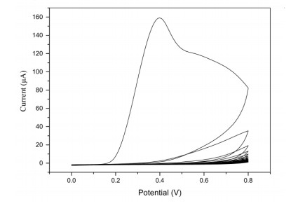
Fig. 3 shows the typical cyclic voltammograms for the electrochemical polymerization of hybrid monomers (resorcinol and o-phenylenediamine) on GC electrode in the presence of TCS. It can be seen that irreversible oxidation reaction of hybrid monomers happened on the surface of GC electrode. In the first cycle, an irreversible oxidation peak appeared at 0.399 V, and this oxidation peak decreased significantly in the second cycle and became unobvious in the subsequent electrochemical polymerization. From the cyclic voltammograms, we can see that the current decreased dramatically with the polymerization proceeding, and an insulating film formed by hybrid monomers on the surface of GC electrode.
As reference, a similar experiment was taken out except adding TCS template. The obtained cyclic voltammograms have no significant difference with the above polymerization curves, because TCS has no electroactivity on GC electrode under the above experiment conditions. Therefore, the structure of TCS does not change during the above reaction process.
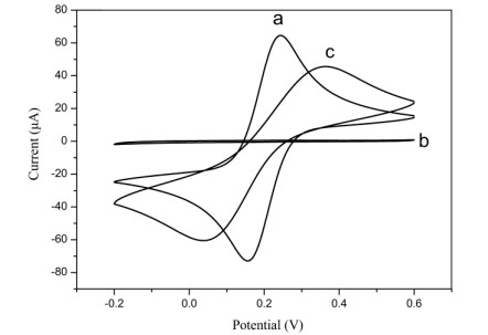
The cyclic voltammograms of bare GC, NIPs/GC and MIPs/GC electrodes were performed in 5 mM potassium ferricyanide aqueous solution (containing 0.2 M KCl), as shown in Fig. 4. In regard to the bare GC electrode, there was a quasi-reversible electrochemical redox reaction of [Fe(CN)6]3-/[Fe(CN)6]4- ion pair appearing in the cyclic voltammograms (Fig. 4a). However, there was almost no electrochemical property as to the NIPs/GC electrode (Fig. 4b), because imprinting cavities could not form without TCS in the polymerization solution. Redox reaction could not take place without ferricyanide reaching the surface of GC electrode due to the blocking function of the compact hybrid monomer film. Compared with the bare GC electrode, an obvious current decrease could be seen for the cyclic voltammograms of the MIPs/GC electrode (Fig. 4c) because the surface of the electrode was covered with nonconducting hybrid monomer film. However, there are imprinting cavities in the film of MIPs/GC electrode, so ferricyanide could reach the surface of GC electrode through the cavities.
The TCS in water was detected through potassium ferricyanide probe solution. Imprinting cavities would be left after the TCS template was extracted from the MIPs/GC electrode. DPV scan was performed on MIPs/GC electrode in potassium ferricyanide solution and the current peak was marked i0. Then, a certain amount of TCS was added into the potassium ferricyanide solution, and the current peak was determined by DPV method after incubating the MIPs/GC electrode in the solution for a certain period of time. When the imprinting cavities were occupied by the TCS molecules in the solution, the current peak would be lower (marked i) because of the decrease of ferricyanide ions accessing to the surface of the electrode. The change of current peak was marked Δi (Δi = i0 – i). The higher the concentration of TCS was, the more the imprinting cavities in the film were occupied and the larger the value of Δi changed.
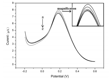
When detecting TCS with the MIPs/GC electrode, the process of TCS occupying the imprinting cavities needed a certain period of time to reach an equilibrium state. Therefore, we studied the influence of incubation time on the DPV current peak. After TCS template was removed, the MIPs/GC electrode was immersed into a potassium ferricyanide solution containing a certain amount of TCS, and DPV was performed between the intervals of time. Fig. 5 shows the results of different incubation time. With the incubation time increased, the current peak of DPV curves decreased. After the incubation time reached 15 min, there was extremely tiny change on the DPV current peak. Therefore, the optimal incubation time was determined to be 15 min in subsequent experiment to detect TCS.
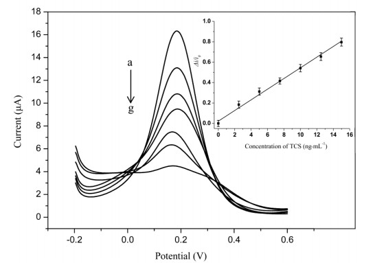
After the TCS template was removed, the MIPs/GC electrode was immersed into a potassium ferricyanide solution containing different amount of TCS, and DPV was performed, respectively, after the electrode was incubated for 15 min. From Fig. 6, we can see that the current peaks of DPV curves decreased with the amount of TCS added because more imprinting cavities were occupied by TCS template molecules. A linear relation was obtained by using the value Δi/i0[1] as Y-axis and the corresponding concentration of TCS as X-axis, as shown in the inset of Fig. 6. The concentration of TCS exhibits good linearity between 0 and 15 ng·mL-1. The calibration linear equation of Δi/i0 = 0.05225c + 0.02225 (r2 = 0.9912). The detection limit of MIPs/GC electrode to TCS was 0.41 ng·mL-1 through calculation (based on S/N = 3).
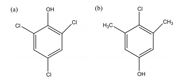
In order to determine the influence of interfering substance to the detection properties of the MIPs/GC electrode, the structural analogues 2, 4, 6-trichlorophenol (TCP) and 4-chloro-3, 5-dimethylphenol (PCMX) (Fig. 7) were used to perform interference experiment. The MIPs/GC electrode was immersed in a 30 mL potassium ferricyanide solution containing 10.0 ng·mL-1 TCS and 0.2 M KCl, DPV was performed and the current peak was 7.05 µA. Then, different amount of interfering substance was added and DPV was performed again to compare the change of current peak. The results are shown in Table 3, from which we can find that the current peaks have little change after different amount interfering substance was added. Therefore, TCP and PCMX had no influence to the TCS detection.
 DownLoad:
CSV
DownLoad:
CSV
| Concentration of interferents (ng·mL-1) | 5.0 | 8.0 | 12.5 |
| Current changes after TCP added (µA) | –0.14 | –0.18 | –0.19 |
| Current changes after PCMX added (µA) | –0.13 | –0.14 | –0.21 |
To verify the applicability of MIPs/GC electrode, a recovery study was carried out on a kind of cosmetic emulsion spiked with a certain amount of TCS. 1.0027 g of cosmetic emulsion was added into 0.1 M NaOH aqueous solution, stirring until dissolution, and metering volume into a 250 mL volumetric flask. 10 mL of the above cosmetic emulsion solution was centrifuged for 5 min with a rotate speed of 10000 rpm. Then 0.50 mL of the upper clear solution was added into 29.50 mL potassium ferricyanide solution containing different amount of TCS, and the TCS was detected by the method described above. The results shown in Table 4 demonstrated that the MIPs/GC electrode can measure TCS in the cosmetic emulsion.
DownLoad:
CSV
| Sample | Amount of TCS (ng·mL-1) | Recovery | |
| Addition | Detectable amount | ||
| 1 | 5.0 | 5.3 | 106% |
| 2 | 10.0 | 10.2 | 102% |
| 3 | 12.0 | 12.3 | 103% |
In this work, computational method was applied to study the interaction between TCS template molecules and single kind of monomers or hybrid functional monomers in the prepolymerization complex. Based on theoretical guidance, hybrid monomers (resorcinol and o-phenylenediamine) were used to construct molecularly imprinted electrochemical sensor to detect TCS. The sensor exhibits good sensitivity and selectivity for TCS with the detection range of 0~15 ng·mL-1 and detection limit of 0.41 ng·mL-1. The synthesized MIPs/GC electrochemical sensor can be applied to detect TCS in real samples such as cosmetic emulsion. Furthermore, molecularly imprinted electrochemical sensors are still in progress in our laboratory, which should attract much interest due to their versatility for future applications.
Liu, Y.; Song, Q. J.; Wang, L. Development and characterization of an amperometric sensor for triclosan detection based on electropolymerized molecularly imprinted polymer. Microchem. J. 2009, 91, 222–226. doi: 10.1016/j.microc.2008.11.007
von der Ohe, P. C.; Schmitt-Jansen, M.; Slobodnik, J.; Brack, W. Triclosan—the forgotten priority substance? Environ. Sci. Pollut. Res. 2012, 19, 585–591. doi: 10.1007/s11356-011-0580-7
Singer, H.; Müller, S.; Tixier, C.; Pillonel, L. Triclosan: occurrence and fate of a widely used biocide in the aquatic environment: field measurements in wastewater treatment plants, surface waters, and lake sediments. Environ. Sci. Technol. 2002, 36, 4998–5004. doi: 10.1021/es025750i
Zhu, X.; Liu, Y.; Luo, G.; Qian, F.; Zhang, S.; Chen, J. Facile fabrication of magnetic carbon composites from hydrochar via simultaneous activation and magnetization for triclosan adsorption. Environ. Sci. Technol. 2014, 48, 5840–5848. doi: 10.1021/es500531c
Wulff, G.; Sarhan, A.; Gimpel, J.; Lohmar, E. Über enzymanalog gebaute polymere, Ⅲ. zur synthese von polymerisierbaren D-glycerinsäurederivaten. Chem. Ber. 1974, 107, 3364–3376. doi: 10.1002/cber.19741071022
Wulff, G.; Sarhan, A. The use of polymers with enzyme-analogous structures for the resolution of racemates. Angew. Chem. Int. Ed. Engl. 1972, 11, 341–344.
Wulff, G. Fourty years of molecular imprinting in synthetic polymers: origin, features and perspectives. Microchim. Acta 2013, 180, 1359–1370. doi: 10.1007/s00604-013-0992-9
Cao, Y.; Feng, T.; Xu, J.; Xue, C. Recent advances of molecularly imprinted polymer-based sensors in the detection of food safety hazard factors. Biosens. Bioelectron. 2019, 141, 111447, 1–18.
Sanjuán, A. M.; Reglero Ruiz, J. A.; García, F. C.; García, J. M. Recent developments in sensing devices based on polymeric systems. React. Funct. Polym. 2018, 133, 103–125. doi: 10.1016/j.reactfunctpolym.2018.10.007
Chen, L. G.; Liu, J.; Zeng, Q. L.; Wang, H.; Yu, A. M.; Zhang, H. Q.; Ding, L. Preparation of magnetic molecularly imprinted polymer for the separation of thtracycline antibiotics form egg and tissue samples. J. Chromatogr. A 2009, 1216, 3710–3719. doi: 10.1016/j.chroma.2009.02.044
Blanco-López, M. C.; Lobo-Castañón, M. J.; Miranda-Ordieres, A. J.; Tuñón-Blanco, P. Electrochemical sensors based on molecularly imprinted polymers. Trac. Trends Anal. Chem. 2004, 23, 36–48. doi: 10.1016/S0165-9936(04)00102-5
Gui, R.; Jin, H.; Guo, H.; Wang, Z. Recent advances and future prospects in molecularly imprinted polymers-based electrochemical biosensors. Biosens. Bioelectron. 2018, 100, 56–70. doi: 10.1016/j.bios.2017.08.058
Piyush, S. S.; Agnieszka, P. L.; Francis, D. S.; Wlodzimierz, K. Electrochemically synthesized polymers in molecular imprinting for chemical sensing. Anal. Bioanal. Chem. 2012, 402, 3177–3204. doi: 10.1007/s00216-011-5696-6
Qader, B.; Baron, M.; Hussain, I.; Sevilla, J. M.; Johnson, R. P.; Gonzalez-Rodriguez, J. Electrochemical determination of disulfoton using a molecularly imprinted poly-phenol polymer. Electrochim. Acta 2019, 295, 333–339. doi: 10.1016/j.electacta.2018.10.127
Beytur, M.; kardasş, F.; Akyildddirim, O.; Özkan, A.; Bankoğlu, B.; Yüksek, H.; Yola, M. L.; Atar, N. A highly selective and sensitive voltammetric sensor with molecularly imprinted polymer based silver@gold nanoparticles/ionic liquid modified glassy carbon electrode for determination of ceftizoxime. J. Mol. Liq. 2018, 251, 212–217. doi: 10.1016/j.molliq.2017.12.060
Yola, M. L.; Cöde, C.; Atar, N. Molecular imprinting polymer with polyoxometalate/carbon nitride nanotubes for electrochemical recognition of bilirubin. Electrochim. Acta 2017, 246, 135–140. doi: 10.1016/j.electacta.2017.06.053
Yola, M. L.; Atar, N. Electrochemical detection of atrazine by platinum nanoparticles/carbon nitride nanotubes with molecularly imprinted polymer. Ind. Eng. Chem. Res. 2017, 56, 7631–7639. doi: 10.1021/acs.iecr.7b01379
Atar, N.; Yola, M. L.; Eren, T. Sensitive determination of citrinin based on molecular imprinted electrochemical sensor. Appl. Surf. Sci. 2016, 362, 315–322. doi: 10.1016/j.apsusc.2015.11.222
Ertan, B.; Eren, T.; Ermiş, İ.; Saral, H.; Atar, N.; Yola, M. L. Sensitive analysis of simazine based on platinum nanoparticles on polyoxometalate/muti-walled carbon nanotubes. J. Colloid Interf. Sci. 2016, 470, 14–21. doi: 10.1016/j.jcis.2016.02.036
Liu, J. B.; Tang, S. S.; Dai, Z. Q.; Wang, Y.; Gao, Q.; Jin, R. F. Computer simulation and experimental investigations of phenobarbital molecular imprinting system. Chin. J. Struct. Chem. 2016, 35, 1840–1848.
Nicholls, I. A.; Anderson, H. S.; Golker, K.; Henschel, H.; Karlsson, B. C. G.; Olsson, G. D.; Rosengren, A. M.; Shoravi, S.; Suriyanarayanan, S.; Wiklander, J. G.; Wikman, S. Rational design of biomimetic molecularly imprinted materials: theoretical and computational strategies for guiding nanoscale structured polymer development. Anal. Bioanal. Chem. 2011, 400, 1771–1786. doi: 10.1007/s00216-011-4935-1
Nicholls, I. A.; Karlsson, B. C. G.; Olsson, G. D.; Rosengren, A. M. Computational strategies for the design and study and molecularly imprinted materials. Ind. Eng. Chem. Res. 2013, 52, 13900–13909. doi: 10.1021/ie3033119
Levi, L.; Raim, V.; Srebnik, S. A brief review of coarse-grained and other computational studies of molecularly imprinted polymers. J. Mol. Recognit. 2011, 24, 883–891. doi: 10.1002/jmr.1135
Su, T. T.; Liu, J. B.; Tang, S. S.; Chang, H. B.; Jin, R. F. Theoretical study on the structures and properties of phenobarbital imprinted polymers. Chin. J. Struct. Chem. 2014, 33, 1421–1430.
Wei, S.; Jakusch, M.; Mizaikoff, B. Investigating the mechanisms of 17β-estradiol imprinting by computational prediction and spectroscopic analysis. Anal. Bioanal. Chem. 2007, 389, 423–431. doi: 10.1007/s00216-007-1358-0
Lu, C.; Tang, Z.; Gao, X.; Ma, X.; Liu, C. Computer-aided design of magnetic dummy molecularly imprinted polymers for solid-phase extraction of ten phthalates from food prior to their determination by GC-MS/MS. Microchim. Acta 2018, 185, 373. doi: 10.1007/s00604-018-2892-5
Rohani, F. G.; Mohadesi, A.; Ansari, M. A new diosgenin sensor based on molecularly imprinted polymer of para aminobenzoic acid selected by computer-aided design. J. Pharmaceut. Biomed. 2019, 174, 552–560. doi: 10.1016/j.jpba.2019.04.044
Wang, Y.; Liu, J.; Tang, S. S.; Jin, R. F. Preparation of melamine molecularly imprinted polymer by computer-aided design. J. Sep. Sci. 2015, 38, 2647–2654. doi: 10.1002/jssc.201500375
Pace, S. J.; Nguyen, E.; Baria, M. P.; Mojica, E. E. Use of computational modeling in the preparation and evaluation of surface imprinted xerogels for binding tetracycline. Microchim. Acta 2015, 182, 69–76. doi: 10.1007/s00604-014-1305-7
Yola, M. L.; Atar, N.; Eren, T.; Karimi-Maleh, H.; Wang, S. Sensitive and selective determination of aqueous triclosan based on gold nanoparticles on polyoxometalate/reduced graphene oxide nanohybrid. RSC Adv. 2015, 5, 65953–65962. doi: 10.1039/C5RA07443F
Motia, S.; Albert-Tudor, I.; Antonio-Ribeiro, P.; Raposo M.; Bouchikhi B.; El-Bari, N. Electrochemical sensor based on molecularly imprinted polymer for sensitive triclosan detection in wastewater and mineral water. Sci. Total Environ. 2019, 664, 647–658. doi: 10.1016/j.scitotenv.2019.01.331
Ramos, A. I.; Braga, S. S.; Almeida-Paz, F. A. Triclosan. Acta Crystallogr. C 2009, 65, O404–O405. doi: 10.1107/S0108270109026511
Frisch, M. J.; Trucks, G. W.; Schlegel, H. B.; Scuseria, G. E.; Robb, M. A.; Cheeseman, J. R.; Scalmani, G.; Barone, V.; Petersson, G. A.; Nakatsuji, H.; Li, X.; Caricato, M.; Marenich, A.; Bloino, J.; Janesko, B. G.; Gomperts, R.; Mennucci, B.; Hratchian, H. P.; Ortiz, J. V.; Izmaylov, A. F.; Sonnenberg, J. L.; Williams-Young, D.; Ding, F.; Lipparini, F.; Egidi, F.; Goings, J.; Peng, B.; Petrone, A.; Henderson, T.; Ranasinghe, D.; Zakrzewski, V. G.; Gao, J.; Rega, N.; Zheng, G.; Liang, W.; Hada, M.; Ehara, M.; Toyota, K.; Fukuda, R.; Hasegawa, J.; Ishida, M.; Nakajima, T.; Honda, Y.; Kitao, O.; Nakai, H.; Vreven, T.; Throssell, K.; Montgomery, J. A. Jr.; Peralta, J. E.; Ogliaro, F.; Bearpark, M.; Heyd, J. J.; Brothers, E.; Kudin, K. N.; Staroverov, V. N.; Keith, T.; Kobayashi, R.; Normand, J.; Raghavachari, K.; Rendell, A.; Burant, J. C.; Iyengar, S. S.; Tomasi, J.; Cossi, M.; Millam, J. M.; Klene, M.; Adamo, C.; Cammi, R.; Ochterski, J. W.; Martin, R. L.; Morokuma, K.; Farkas, O.; Foresman, J. B.; Fox, D. J. Gaussian, Inc.; Wallingford CT, Gaussian 09, Revision A. 02 2016.

Figure 1 Optimized structures of (a) TCS template, (b) resorcinol monomer, (c) o-phenylenediamine monomer (C-dark grey, O-red, N-blue, Cl-green, H-light grey)

Figure 2 Conformation of the complex formed by (a) one TCS and two resorcinol molecules, (b) one TCS and two o-phenylenediamine molecules, (c) hybrid monomers (one resorcinol and one o-phenylenediamine molecules) (C-dark grey, O-red, N-blue, Cl-green, H-light grey)

Figure 3 Typical cyclic voltammograms for the electrochemical polymerization of hybrid monomers on GC electrode in the presence of TCS

Figure 4 Cyclic voltammograms of (a) bare GC electrode, (b) NIPs/GC electrode, (c) MIPs/GC electrode

Figure 5 Results of different incubation time for MIPs/GC electrode (Incubation time: a-0min, b-5min, c-10min, d-15min, e-20min)

Figure 6 DPV curves of MIPs/GC electrode in different amounts of TCS (TCS concentration: a-0ng·mL-1, b-2.5ng·mL-1, c-5ng·mL-1, d-7.5ng·mL-1, e-10ng·mL-1, f-12.5ng·mL-1, g-15ng·mL-1)

Figure 7 Structural analogues (a) 2, 4, 6-trichlorophenol (TCP), (b) 4-chloro-3, 5-dimethylphenol (PCMX)
Table 1. Structural Parameters of TCS Calculated at the CAM-B3LYP Level and Available Experimental Data (R and Φ Are Bond Lengths and Bond Angles, respectively. Δ is the Difference between the Calculated and Available Experimental Data)
| CAM-B3LYP/6-31G(d, p) | Exp.a | Δ | |
| R (Ǻ) | |||
| C1–O2 | 1.37273 | 1.35301 | 0.01972 |
| C3–Cl1 | 1.74044 | 1.74556 | 0.00512 |
| C6–O1 | 1.39642 | 1.37631 | 0.02011 |
| C7–O1 | 1.37885 | 1.36410 | 0.01475 |
| C12–Cl3 C10–Cl12 |
1.72847 1.74062 |
1.73707 1.74612 |
0.00860 0.00550 |
| Φ (°) | |||
| O2–C1–C6 | 117.95046 | 117.24838 | 0.70208 |
| O2–C1–C2 | 122.51881 | 123.46024 | 0.94143 |
| C2–C3–Cl1 | 118.42176 | 118.74993 | 0.32817 |
| C4–C3–Cl1 | 119.44432 | 119.67298 | 0.22866 |
| O1–C6–C5 | 119.71959 | 119.42554 | 0.29405 |
| O1–C7–C8 | 124.54448 | 123.89221 | 0.65227 |
| C7–C12–Cl3 | 119.88970 | 119.79042 | 0.09928 |
| C11–C12–Cl3 | 118.71799 | 119.52212 | 0.60839 |
| C11–C10–Cl2 | 118.09670 | 119.32638 | 1.22968 |
| C9–C10–Cl2 | 120.64145 | 119.87432 | 0.76713 |
| a Ref. [32]. | |||
 下载: 导出CSV
Table 2. Chosen Monomer and Their Computed Energies in the Absence and Presence of TCS in Gas Phase
| Molecules | E (Hartree) | ΔE (Hartree) | ΔE (kJ·mol-1) |
| TCS | –1992.21258261 | ||
| o-phenylenediamine | –342.78586927 | ||
| Resorcinol | –382.51525868 | ||
| TCS(o-phenylenediamine)2 | –2677.81120083 | –0.02687968 | –70.57259984 |
| TCS(resorcinol)2 | –2757.26564277 | –0.02254280 | –59.1861214 |
| TCS(o-phenylenediamine-co-resorcinol) | – 2717.54214663 | –0.07890196 | –207.15709598 |
下载: 导出CSV
Table 3. Influence of Interferents on the DPV Response of 10.0 ng·mL-1 TCS
| Concentration of interferents (ng·mL-1) | 5.0 | 8.0 | 12.5 |
| Current changes after TCP added (µA) | –0.14 | –0.18 | –0.19 |
| Current changes after PCMX added (µA) | –0.13 | –0.14 | –0.21 |
下载: 导出CSV
Table 4. Application of the MIPs/GC Electrode to Determine TCS in Cosmetic
| Sample | Amount of TCS (ng·mL-1) | Recovery | |
| Addition | Detectable amount | ||
| 1 | 5.0 | 5.3 | 106% |
| 2 | 10.0 | 10.2 | 102% |
| 3 | 12.0 | 12.3 | 103% |
下载: 导出CSV

 扫一扫看文章

扫一扫关注我们

 下载:
下载: