State Key Laboratory of Coordination Chemistry, Jiangsu Key Laboratory of Advanced Organic Materials, School of Chemistry and Chemical Engineering, Nanjing University, Nanjing 210023, China
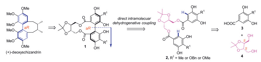
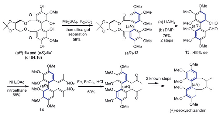
An intramolecular dehydrogenative homo- and hetero-coupling of phenols has been successfully developed for quick preparation of enantiopure axial diphenols under mild Cu(Ⅱ)-mediated conditions, using ((4S, 5S)-2,2-dimethyl-1,3-dioxolane-4,5-diyl)dimethanol as the chiral auxiliary. The commercially available (R)-α-methylbenzylamine was identified as the best amine ligand for Cu(Ⅱ) in the reactions. A variety of homo/hetero bis-dihydroxylbenzoate substrates were examined, affording the corresponding axially chiral diphenols with satisfactory to excellent diastereomeric ratios, and a representative scalable preparation was also attempted. A formal synthesis of natural product (+)-deoxyschizandrin has been achieved in this work using one axially chiral diphenol as the synthetic intermediate.
Rechargeable metal-air batteries (including zinc-air batteries, ZABs) as renewable energy conversion systems are attracting more and more attention for their pollution-free feature, technical sustainability and high energy conversion efficiency [1–4]. Oxygen evolution and reduction reactions (OER/ORR) are the two major processes that determine the performance of ZABs [4–6]. ORR or OER needs to conduct an inherently-complex charge transfer process, which is characterized by hysteresis kinetics, and thus requires an inherent overpotential to promote the ORR/OER processes [7,8]. Although Pt/C and RuO2 are usually considered as the most advanced ORR and OER catalysts, respectively, their high cost and scarcity have inhibited their widespread commercialization [9–12]. Meanwhile, non-precious metal catalysts are prone to activity degradation in the electrolytes, resulting in a low active surface area and the corrosion of active species [13]. Moreover, the active components are inevitably dissolved under harsh conditions, making the catalytic activity and stability of the catalysts much weaker [14]. Therefore, exploring non-precious metal-based catalysts with excellent catalytic performance and stability is a feasible way to accelerate the development of ZABs.
Due to their high stability and excellent electrochemical performance, the first-row transition metals-based compounds such as oxides, sulfides, and phosphides are often considered as the most powerful replacements for noble metal-based electrocatalysts [15,16,39]. Pyrite-type sulfides (PTSs) have been identified as the most efficient ORR/OER catalysts currently [16–18]. Since PTSs are typically cubic crystal system semiconductors, they possess divalent anion units and octahedral coordination cations. However, the inherent electrocatalytic performance of PTSs remains unsatisfactory because of their low electro-conductibility, slow electron transfer process and easy oxidation of surface atoms [19]. Cobalt pyrite (CoS2) has been reported as a bifunctional catalyst for ORR/OER, however, its catalytic activity is easily inhibited by the accumulation and buildup of Co-species nanoparticles. In addition, its durability is also not satisfactory due to the dissolution of cations and external sulfur substances during the oxidation reaction [20]. To overcome these drawbacks, bifunctional pyrite-based catalysts are often coated with a thin conductive layer, such as amorphous active materials or carbon-based materials, which is considered an effective strategy to prevent catalyst aggregation and dissolution as well as to improve catalyst durability [16–20]. Reduced graphene oxide (rGO) with high electro-conductibility and specific surface area makes it a potential catalyst carrier [20]. As demonstrated previously, the stability of metal nanoparticles can be enhanced by the coating of rGO layer on CoS2, and the valence electrons of Co can readily enter the carbon structure and cooperate with the nitrogen (N)-doped rGO to energetically exert catalytic effects [20,21]. In addition, the carbon layer prevents the reunion/corrosion of CoS2, thus improving its stability. Thus, when the conductive carbon is uniformly coated on the surface of PTSs, it can energetically improve the conductivity and catalytic performance of the catalyst [20–23].
However, after the coating of conductive carbon layer, it is not clear whether the mass/charge transports to the active sites on PTSs will be enhanced. Therefore, designing bifunctional PTSs-based electrocatalysts still remains a great challenge. It is well known that the number of exposed active sites and the intrinsic activity of each active component govern the catalytic activity of catalyst [24]. Therefore, the design of PTSs-based porous catalysts, particularly with a high electro-conductibility and a variety of electrochemically active sites including metallic species and sulfides, is very important for oxygen electrocatalysis [24–26]. As reported previously, porous ovoid-shell hollow pyrite spheres (with carbon coating) show enhanced ORR/OER activities with small overpotential gaps, fast kinetics and excellent cycling stability in rechargeable ZABs [24,27–30]. These porous PTSs catalysts with thoroughly-exposed active sites can effectively overcome the intrinsic activation barriers and promote the reaction kinetics for OER/ORR as their d-band centers are near to the Fermi energy level. In this regard, by optimizing the structural properties, the porous yolk-shell nanostructure with an abundant internal space, a large specific surface area and a big reactants-catalyst contact area is quite suitable for oxygen reduction/evolution.
Here, we suggest a feasible strategy for in-situ formation of nucleation sites by quantitative amino modification on the surface of yolk-shell structured pyrite-type CoS2 (CoS2 YSS) to graft highly-conductive N-doped (needle-like) carbon (CoS2 YSS@NC). To our knowledge, this is the first attempt to resolve the issue of poor electrical conductivity of CoS2 YSS for ORR/OER. The stable yolk-shell structure should facilitate the transport of electrolytes, the active sites exposed on the exterior/interior-exterior (three) surfaces, and the mass transfer between oxygen molecules and electrodes [31]. The close contact between CoS2 YSS and NC can generate a desirable coupling effect to regulate the charge transfer pathway and prevent the dissolution of active sites protected by the needle-like carbon layer, which accordingly reduce the polarization to obtain the promising bifunctional activity and stability [32]. In addition, the rechargeable ZAB assembled with CoS2 YSS@NC cathode should exhibit efficient discharge and charging processes. It develops a convenient method for constructing highly-conductive PTSs-based bifunctional catalysts.
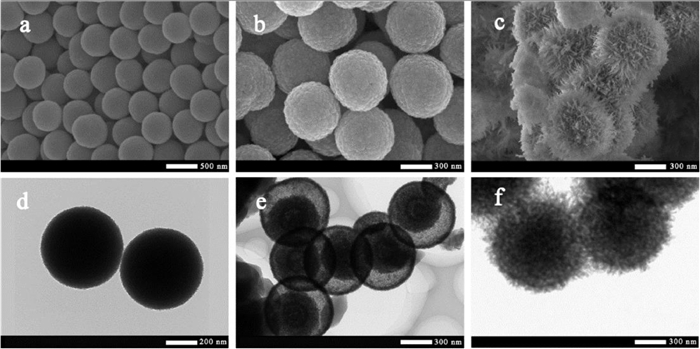
The synthesis process of CoS2 YSS@NC composites is shown in Fig. S1 (The detailed preparation procedures, material characterizations and electrochemical tests are introduced in Supporting information). The structures and morphologies of precursors and as-made catalysts are illustrated in Fig. 1. In Figs. 1a and d (field emission scanning electron microscope (FESEM) and transmission electron microscope (TEM) images), the surface of the uniformly-distributed Co-G SS with an average size of approximately 600 nm is very smooth. The etching of Co-G SS is conducted by using ammonium hydroxide as an etchant. Figs. 1b and e show that after the etching and 2 h of low-temperature sulfidation of the precursor Co-G SS, CoS2 YSS basically retains the original shape of the spheres and shows an obvious gap between the solid core and the rough shell. It is clearly seen that the shell of CoS2 YSS is approximately 30.0 nm. As shown in Fig. 1c, the surface of CoS2 YSS is uniformly coated by the urchin-like N-doped carbon needles after sulfidation at 350 ℃. Moreover, the yolk-shell structure of CoS2 YSS@NC-0.5 is also observed in TEM image (Fig. 1f). This special structure should facilitate the exposure of active sites to enhance the electrocatalytic activity. The pores in the shell should provide abundant mass transfer pathways, which are very favorable for electrolyte permeation and intermediate transfer in the electrocatalytic process [20,33–35,40]. As reported previously, the amino groups of Co-G-A@GO are used as nucleation sites for coupling GO, which is subsequently reduced to rGO on the surface of CoS2 YSS [18,41]. Control experiments (Fig. S2 in Supporting information) show that excessive NH3·H2O (more amino groups may be provided on the surface of Co-G-A@GO) also yields another urchin-like CoS2 YSS@NC-0.5 with the aggregated NC needles (thicker) coated on the surface of CoS2 YSS, and without NH3·H2O, the NC-aggregated spheres are obtained, suggesting that NH3·H2O should yield a useful support for the growth of pyrite-based hybrids.
Figure 1
Figure 1.
SEM images of Co-G (a), CoS2 YSS (b) and CoS2 YSS@NC-0.5 (c); TEM images of Co-G (d), CoS2 YSS (e) and CoS2 YSS@NC-0.5 (f).
In Fig. S3a (Supporting information), the high-resolution HRTEM images of CoS2 YSS@NC-0.5 further shows the gap between yolk and shell, and the obvious exterior layer of grafted N-doped carbon, further demonstrating that the well-combined structure of CoS2 YSS@NC-0.5 is constructed. The hollow structure of CoS2 YSS can provide an interior place for reactions (i.e., the desirable confinement effect) during the electrocatalysis process. In Figs. S3b and c (Supporting information), the lattice spacing of 0.33 and 0.15 nm are ascribed to the (002) and (103) facets of graphite, respectively, while the lattice spacing of 0.24 nm corresponds to the (210) facet of CoS2, which are further confirmed by the following X-Ray diffraction (XRD) results. It also shows that the NC shell is closely combined with the CoS2 YSS and the mall ravines on the surface of CoS2 YSS are fully filled by the thin NC layers. As illustrated in the selection area electron diffraction patterns (Fig. S3d in Supporting information), the two diffraction rings (outside and inside) are ascribed to the (111) and (210) crystal planes of CoS2. The high angle angular dark field-scanning TEM elemental mapping images (Figs. S3e–k in Supporting information) show that C, N, O, S and Co elements are uniformly distributed on the surface of CoS2 YSS@NC-0.5. The elemental mapping images of CoS2 YSS basically shows the same results (Fig. S4 in Supporting information). It further confirms that the CoS2 YSS is well wrapped by the NC shell. Fig. S3e distinctly shows an eccentric yolk-shell structure and a hollow space close to half the volume of the sphere. The unique yolk shell structure can provide abundant pathways to enhance the mass transfer (including the transport of intermediates) efficiency, which should also promote the usage of active sites dispersed on the interior/exterior surfaces [42,43].
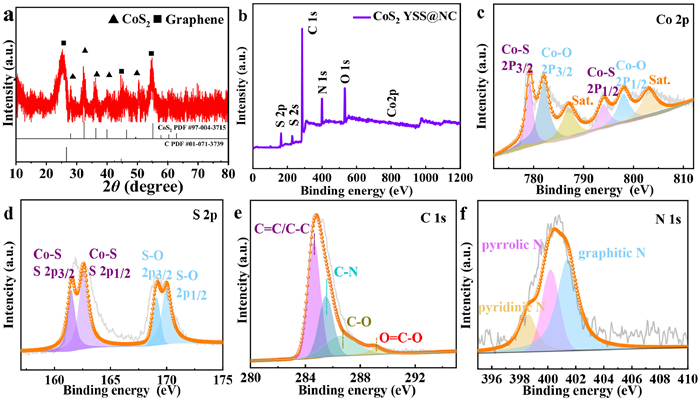
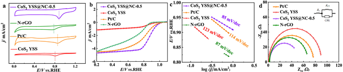
In Fig. 2a, the diffraction peaks at around 27.96°, 32.39°, 36.33°, 40.02° and 54.89° are ascribed to (111), (200) (210), (211), and (311) crystal planes of CoS2 (JCPDS card No. 41–1471), respectively [36,37]. In addition, the diffraction peaks at around 26.51°, 45.37°, 50.56° and 54.61° correspond to (002), (101), (102), and (004) planes of graphite (JCPDS card No. 41–1487), respectively. These results confirm that the desirable components in CoS2 YSS@NC-0.5 catalyst are successfully obtained. Obviously, there is no impurity peaks, confirming that the precursors are well vulcanized to produce CoS2 YSS@NCs-0.5. The well-crystallized components in CoS2 YSS@NC-0.5 should exhibit a promising catalytic activity due to the synergies between the two components [38]. Fig. 2b (X-ray photoelectron spectroscopy (XPS)) verifies the co-existence of Co, S, C, N, and O elements in CoS2 YSS@NC-0.5. Figs. S5 and S6 (Supporting information) show the high-resolution XPS spectra of Co 2p, S 2p, C 1s and N 1s of other CoS2 YSS@NC-X catalysts. Peak fit analysis of the Co 2p spectrum in Fig. 2c indicates the presence of two chemical states of Co. The two major peaks at around 779.2 (2p3/2) and 794.5 (2p1/2) eV correspond to the Co-S bond, while the peaks at around 781.2 and 797.7 eV are ascribed to the Co-O bond. The two double peaks at around 786.6 and 803.1 eV correspond to the satellite peaks of Co 2p3/2 and Co 2p1/2, respectively [24]. It is noteworthy that the binding energy of Co 2p3/2 (~779.2 eV) is higher than that of Co0 (778.2 eV), implying that Co atom may be slightly positively charged (Coδ) [24]. The S 2p spectrum can be decomposed into four peaks. The two peaks at around 161.5 and 162.6 eV correspond to the Co-S bond, while the other two peaks at around 168.9 and 169.8 eV are ascribed to the S-O bond originated from the surface oxidation of S element (Fig. 2d). The binding energy of S 2p3/2 (161.5 eV) is lower than that of S0 (162.6 eV), which demonstrates the presence of Sδ− in CoS2 YSS@NC-0.5. Therefore, it can be inferred that electron may transfer from Co to S during ORR/OER because of the high electronegativity of the S atom [44]. As indicated by these XPS results, there should be a strong interaction between CoS2 and NC, which contributes to the enhancement of ORR/OER catalytic activities. For C 1s spectrum, four typical peaks are observed at around 284.6, 285.5, 286.6 and 289.0 eV, corresponding to C=C/C-C, C-N, C-O and O=C-O groups, respectively (Fig. 2e). As reported previously, the doping of N atoms to carbon skeleton during sulfidation process can positively increase the electrocatalytic activity [45]. O-containing functional groups (O=C-O) can optimize the surface properties of the catalyst, promote the O2/OH− adsorption ability, and promote the ORR/OER activities [46]. In Fig. 2f, the N 1s spectrum is well decomposed into three species at around 398.6, 400.2 and 401.4 eV, which correspond to pyridine N, pyrroline N and graphite N in the carbon matrix, respectively. The specific surface area (SSA) and pore structure are obtained using N2 adsorption-desorption isotherms (Figs. S7a–c and Table S2 in Supporting information). Cyclic voltammetry (CV) tests are performed to study the electrocatalytic ORR activities of the prepared CoS2 YSS@NC catalysts (Fig. 3a and Fig. S8a in Supporting information). CoS2 YSS@NC-0.5 shows a reduction peak at 0.87 V, which is positive than those of Pt/C (0.84 V), CoS2 YSS (0.81 V) and N-rGO (0.77 V), indicating that the active sites (Co-S) at the interfaces mainly contribute to the promising ORR activity. Moreover, the introduction of a highly conductive heteroatom (N)-functionalized carbon shell can activate the CoS2 on the surface of the yolk-shell (synergies between Co-S and N species) and accelerate the charge transfer between oxygen molecules and electrode. Moreover, the unique yolk shell structure with high SSA and pore volume will promote the penetration of electrolyte into the catalyst (active sites) to thereby accelerate the ORR kinetics. In Fig. 3b and Fig. S8b (Supporting information), linear sweep voltammetry (LSV) tests are used to further evaluate the electrocatalytic performances of the four catalysts. Results show that the CoS2 YSS@NC-0.5 shows promising onset potential (Eonset) of 0.99 V and half-wave potential (E1/2) of 0.88 V (The current densities adopted for the determination of Eonset and E1/2 are −0.23 and −1.98 mA/cm2, respectively), which are significantly positive than those of commercial Pt/C (Eonset = 0.98 V and E1/2 = 0.85 V) and CoS2 YSS (Eonset = 0.96 V and E1/2 = 0.83 V). From this, it is inferred that the strong synergistic effects between CoS2 and rGO, as well as the clever design of the yolk-shell structure give CoS2 YSS@NC-0.5 a larger electrolyte-electrode contact area for oxygen adsorption/desorption, thus promoting the mass transport efficiency and catalytic activity. The H2SO4 leaching experiments are performed to clarify the main active species in CoS2 YSS@NC-0.5 for ORR. As shown in Fig. S9 (Supporting information), after the catalyst is leached by 0.5 mmol/L H2SO4 for 12 h, the E1/2 value in LSV curve shows a negative shift of 50 mV. After H2SO4 leaching, the ORR activity is obviously affected because the Co species are completely removed from the catalyst. Therefore, it indicates that the Co species (Co-S and/or Co-O bonds) play the important roles in catalyzing ORR.
Figure 2
Figure 2.
XRD patterns (a) of CoS2 YSS@NC-0.5. XPS survey spectrum (b) and high resolution XPS spectra of Co 2p (c), S 2p (d), C 1s (e) and N 1s (f) for CoS2 YSS@NC-0.5.
Figure 3.
(a) CV curves of CoS2 YSS@NC-0.5, CoS2 YSS, N-rGO and Pt/C in an O2-saturated 0.1 mol/L KOH solution at a scan rate of 10 mV/s. (b) LSV curves (5 mV/s and 1600 rpm) of CoS2 YSS@NC-0.5, CoS2 YSS, N-rGO and Pt/C in an O2-saturated 0.1 mol/L KOH solution. (c) Tafel plots of CoS2 YSS@NC-0.5 and Pt/C. (d) Nyquist curves of CoS2 YSS@NC-0.5, CoS2 YSS and Pt/C in an O2-saturated 0.1 mol/L KOH solution at a scan rate of 5 mV/s with a rotation rate of 1600 rpm.
Tafel slope is plotted to investigate the ORR kinetics of CoS2 YSS@NC-0.5 (Fig. 3c). It shows that the Tafel slope of CoS2 YSS@NC-0.5 (85 mV/dec) is smaller than that of Pt/C (108 mV/dec). The fast mass transfer through the special porous yolk-shell structure (internal finite space) and NC surface makes the CoS2 YSS@NC-0.5 possess efficient ORR kinetics. The radius of the semicircular Nyquist plot is plotted to obtain the charge transfer resistance (RCT) between the electrode and electrolyte interface. In Fig. 3d, the RCT values of CoS2 YSS@NC-0.5, CoS2 YSS and Pt/C are 43.84, 75.72 and 89.1 Ω, respectively. The lower RCT value implies the better charge transfer capability of CoS2 YSS@NC-0.5, which should be ascribed to the homogeneous coating of highly-conductive NC to form a closely-contacted CoS2-NC bridge, leading to a better electro-conductibility that facilitates the electron transfer. The surface/interface engineering for CoS2 YSS and NC can modulate the charge transfer pathways and generate more active sites, which accordingly reduce the polarization to promote the kinetic process for ORR. More ORR tests and discussions are provided in the Supporting Information (Figs. S10–S12 in Supporting information).
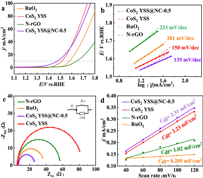
The electrochemical OER activity is fully evaluated in a standard testing system using a 1.0 mol/L KOH solution. In Fig. 4a and Fig. S13 (Supporting information), CoS2 YSS@NC-0.5 exhibits a superior OER overpotential of 244 mV at 10 mA/cm2, which is smaller than those of RuO2 (354 mV), N-rGO (427 mV), CoS2 YSS-0.3 (327 mV), CoS2 YSS-1 (345 mV) and CoS2 YSS (286 mV). As reported previously, the promising activities of these as-prepared catalysts are ascribed to the in-situ formation of the uniformly-distributed oxyhydroxide (CoOOH) on the surface [42,43].
Figure 4
Figure 4.
(a) LSV curves of CoS2 YSS@NC-0.5, CoS2 YSS, N-rGO and RuO2 in 1 mol/L KOH solution for OER (2 mV/s and 1600 rpm). (b) Tafel plots of CoS2 YSS@NC-0.5, CoS2 YSS, N-rGO and RuO2. (c) Nyquist curves of CoS2 YSS@NC-0.5, N-rGO and RuO2 at an amplitude of 5 mV with a rotation rate of 1600 rpm. (d) Linear plots of scan rates vs. current density for CoS2 YSS@NC-0.5, CoS2 YSS, N-rGO and RuO2 in 1 mol/L KOH electrolyte.
Thus, during the transformation of CoS2 to oxyhydroxide at positive potentials, and the sulfur (S) in pyrite is oxidized to form the oxidized S species, and a small amount of oxide remains in the lattice near the Co site, thus improving the kinetic properties of OER [47,48]. In addition, the hollow yolk-shell structure of CoS2 leads to the particular distribution of active species (CoOOH) and the accelerating release of O2 molecules, which favor the restoration of the reaction interfaces to enhance the OER activity [47]. Moreover, this yolk-shell structure should confine the reactants within the shell to thereby exert a promising driving force for the OER. As shown in Fig. 4b, the Tafel slope of CoS2 YSS@NC-0.5 (135 mV/dec) is lower than those of CoS2 YSS (150 mV/dec), N-rGO (223 mV/dec) and RuO2 (201 mV/dec). It indicates that CoS2 YSS@NC-0.5 has a significantly fast OER dynamics, allowing it to be a promising catalyst at high operating currents. In Fig. 4c, CoS2 YSS@NC-0.5 has a small RCT (25.6 Ω) than those of RuO2 (35.85 Ω), CoS2 YSS (80.64 Ω) and N-rGO (56.65 Ω). The lower resistance corresponds to a higher charge transfer efficiency during OER, indicating that the introduction of highly-conductive N-doped carbon can enhance the charge transfer from the internal active species to the external NC, and also change the surface properties of the CoS2 YSS, which accordingly modulate the OER catalytic activity of CoS2 YSS@NC-0.5.
The electrochemical surface areas (ECSAs) obtained from CV tests (Fig. S14 in Supporting information) are used to reveal the number of intrinsically active sites of the catalyst. It is known that the ECSA is positively correlated with double-layer capacitance (Cdl), and the slope of the linearly-fitted curve is calculated by the Cdl to study the activity of the catalyst. As shown in Fig. 4d, the Cdl values of CoS2 YSS@NC-0.5, CoS2, N-rGO and RuO2 are 2.31, 2.23, 1.02 and 0.205 mF/cm2, respectively. Accordingly, the ECSA values of CoS2 YSS@NC-0.5, CoS2, N-rGO and RuO2 are 57.75, 55.75, 25.5 and 5.125 cm2, respectively. These results show that the unique layer-yolk shell structure leads to a uniform dispersion of electrocatalytically active sites exposed on CoS2 YSS@NC-0.5 and the incorporation of the highly-conductive carbon layer greatly enhances the electron transfer rate on the surface, which effectively accelerates the conversion of OH− to O2 at the gas/catalyst/reactants triple-phase boundary. More OER tests and discussions are introduced in the Supporting Information (Fig. S15 in Supporting information).
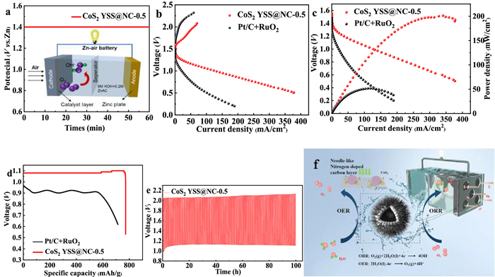
A primary ZAB is constructed to demonstrate the application perspective of CoS2 YSS@NC-0.5 as a bifunctional catalyst within a ZAB. The primary ZAB using CoS2 YSS@NC-0.5 as the air electrode exhibits an open-circuit potential (OCP) as high as approximately 1.4 V (Fig. 5a). Fig. 5b displays the charge and discharge polarization curves for ZABs with CoS2 YSS@NC-0.5 and Pt/C+RuO2. A much lower charge-discharge voltage gap is obtained by CoS2 YSS@NC-0.5 cathode due to its robust bifunctional activity, suggesting a promising rechargeability. As shown in Fig. 5c, the power density maps are made from the discharge polarization curves, and the maximum power density (202 mW/cm2) produced by CoS2 YSS@NC-0.5 catalyst is super to that of commercial Pt/C+RuO2 (52 mW/cm2) under the same condition. The full-discharge curves of ZABs are plotted in Fig. 5d. The specific capacity (normalized by the mass of consumed zinc) of ZAB with CoS2 YSS@NC-0.5 cathode reaches as high as 772.5 mAh/g, which is super to that of Pt/C+RuO2 (714.7 mAh/g) at 10 mA/cm2, indicating that it has a good rate capability. Both rechargeability and cyclic durability are important for evaluating the performance of catalyst in ZABs. By cycling at 10 mA/cm2, the ZAB with CoS2 YSS@NC-0.5 catalyst exhibits an initial discharge potential of 1.11 V and a charge potential of 2.04 V (Fig. 5e). Moreover, the CoS2 YSS@NC-0.5 air cathode shows a slight performance loss after tested at 10 mA/cm2 for 100 h (297 cycles, Fig. 5e), indicating that the CoS2 YSS@NC-0.5 catalyst has a significant cycle stability. As shown in Fig. 5f, the electrical conductivity of the catalyst is greatly enhanced by the introduction of needle-like highly conductive carbon, which also plays a synergistic role with CoS2 to improve the ORR/OER activities.
Figure 5
Figure 5.
(a) Open-circuit plots of primary ZABs assembled with different catalysts. (b) Performances of rechargeable ZABs (polarization curves at 10 mV/s). (c) Discharge polarization curves and corresponding power densities of ZABs with CoS2 YSS@NC-0.5 and Pt/C+RuO2 catalysts. (d) Discharge curves of ZABs with CoS2 YSS@NC-0.5 and Pt/C+RuO2 catalysts at 10 mA/cm2. (e) Galvanostatic charge-discharge curve of CoS2 YSS@NC-0.5-based rechargeable ZAB. (f) ORR/OER mechanisms on CoS2 YSS@NC-0.5.
In summary, N-doped carbon needles-coated pyrite-type sulfide (CoS2 YSS@NC) with a porous yolk shell structure is successfully synthesized using a hydrothermal etching strategy. The NC coating reconfigures the structure of CoS2 YSS to enhance the ORR activity with a promising E1/2 of 0.88 V. Notably, CoS2 YSS@NC shows higher ORR activity and durability than CoS2 alone. The significant ORR activity and durability of CoS2 YSS@NC, along with a low OER overpotential of 244 mV at 10 mA/cm2, make it a potential catalyst candidate for ZAB. A rechargeable ZAB with the CoS2 YSS@NC cathode shows a high open-circuit voltage of 1.4 V, a small charge/discharge voltage gap of 0.5 V, and a promising long-term stability up to 100 h without obvious polarization. The porous yolk-shell structure of CoS2 YSS@NC can expose more active sites for ORR/OER and provide smooth pathways for the fast transport of intermediates. Therefore, this study may stimulate the studies on the functionalized pyrite-type sulfides to design efficient catalysts for ZAB.
Declaration of competing interest
The authors declare that they have no known competing financial interests or personal relationships that could have appeared to influence the work reported in this paper.
Acknowledgments
We acknowledge the support by National Natural Science Foundation of China (Nos. 52070074 and 21806031), Outstanding Youth Fund of Heilongjiang Province (No. JQ2022E005), LongJiang Scholars Program (No. Q201912), Open Project of State Key Laboratory of Urban Water Resource and Environment, Harbin Institute of Technology (No. HC202144), and Graduate Student Innovation Research Projects of Heilongjiang University (No. YJSCX2022-219HLJU).
Supplementary materials
Supplementary material associated with this article can be found, in the online version, at doi:10.1016/j.cclet.2023.109236.
References
[1]
(a) G. Bringmann, A.J.P. Mortimer, P.A. Keller, et al., Angew. Chem. Int. Ed. 44 (2005) 5384-5427; (b) G. Bringmann, M.C. Günther, O. Schupp, S. Taster, Biaryls innature: a multifacettedclass of stereochemically, biosynthetically, and pharmacologically intriguing secondary metabolites, in: W. Herz, H. Falk, G.W. Kirby, R.E. Moore (Eds.), Progress in the Chemistry of Organic Natural Products, 82, Springer, New York, 2001, pp. 1-293; (c) G. Bringmann, T. Gulder, T.A.M. Gulder, M. Breuning, Chem. Rev. 111 (2011) 563-639; (d) F. Lv, Z.J. Yao, Sci. China Chem. 60 (2017) 701-720.
[2]
(a) T. Qin, S.L. Skraba-Joiner, Z.G. Khalil, et al., Nat. Chem. 7 (2015) 234-240; (b) B.B. Liau, B.C. Milgram, M.D. Shair, J. Am. Chem. Soc. 134 (2012) 16765-16772.
(a) T. Biftu, B.G. Hazra, R. Stevenson, J. Chem. Soc. Perkin Trans. I 1 (1979) 2276-2281; (b) T. Takeya, T. Okubo, S. Nishida, S. Tobinaga, Chem. Pharm. Bull. 33 (1985) 3599-3607.
(a) J. Brussee, J.L.G. Groenendijk, J.M. teKoppele, A.C.A. Jansen, Tetrahedron 41 (1985) 3313-3319; (b) M. Smrčina, M. Lorenc, V. Hanuš, P. Sedmera, P. Kočovský, J. Org. Chem. 579 (1992) 1917-1920; (c) Z. Xu, M.C. Kozlowski, J. Org. Chem. 67 (2002) 3072-3078; (d) X.L. Li, J. Yang, M.C. Kozlowski, Org. Lett. 3 (2001) 1137-1140; (e) P. Miko, J. Roithová, D. Schröder, J. Lemaire, H. Schwarz, M.C. Holthausen, Chem. Eur. J. 14 (2008) 4318-4327; (f) M. Nakajima, I. Miyashi, K. Kanayama, S. Hashimoto, J. Org. Chem. 64 (1999) 2264-2271.
[10]
(a) N. Asakura, S. Fujimoto, N. Michihata, et al., J. Org. Chem. 76 (2011) 9711-9719; (b) T. Hirokane, Y. Hirata, T. Ishimoto, K. Nishii, H. Yamada, Nat. Commun. 5 (2014) 3478.
[11]
(a) B.H. Lipshutz, B. James, S. Vance, I. Carrico, Tetrahedron Lett. 38 (1997) 753-756; (b) B.H. Lipshutz, Y.J. Shin, Tetrahedron Lett. 39 (1998) 7010-7020.
[12]
(a) Y. Kasai, N. Michihata, H. Nishimura, T. Hirokane, H. Yamada, Angew. Chem. Int. Ed. 51 (2012) 8026-8029; (b) N. Michihata, Y. Kaneko, Y. Kasai, et al., J. Org. Chem. 78 (2013) 4319-4328; (c) H. Takeuchi, K. Mishiro, Y. Ueda, et al., Angew. Chem. Int. Ed. 54 (2015) 6177-6180; (d) B. Fering, H. Wynberg, Bioorg. Chem. 7 (1978) 397-408.

 Login In


 DownLoad:

 DownLoad: