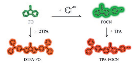
Scheme 1.
Molecular structures and design routes.
Enhanced deep-red emission in donor-acceptor molecular architecture: The role of ancillary acceptor of cyanophenyl
Yue Shen , Xiaohui Tang , Yuwei Xu , Haichao Liu , Shitong Zhang , Bing Yang , Yuguang Ma

High-efficiency red light-emitting materials have attracted significant interest because of their extensive applications in the field of organic light-emitting diodes (OLEDs) [1-7], organic solid-state lasers [8], chemical and biological sensors [9, 10]. In the past decades, however, it is a great challenge to obtain high-performance red light-emitting materials in terms of both high efficiency and pure red color simultaneously. The reason is that intrinsic narrow band-gap of red fluorescent molecules inherits small energy difference between excited state and ground state, which readily suffers from large non-radiative internal conversion rate (κIC)according to the energy gap law [11, 12].
The previous molecular design strategy of red fluorescent molecules was mainly focused on the large π-conjugated compounds. Such molecules generally inherit enhanced aggregation-caused quenching (ACQ) in solid state due to the strong intermolecular π-π stacking [13, 14]. Recently, one of the most common methods of designing deep-red fluorescent molecules is to construct strong intramolecular charge transfer (ICT) com-pounds with donor-acceptor (D-A) structure [5, 15-20]. Based on energy level difference between the highest occupied molecular orbital (HOMO) of donor and the lowest unoccupied molecular orbital (LUMO) of acceptor, the emission band gap can be finely tuned in a wide range according to the choice of donor and acceptor units in D-A molecules. To obtain narrow-band-gap light-emitting materials, an ancillary acceptor should be incorporated into D-A system, which is especially worth trying for high-efficiency deep-red D-A materials.
The readily functionalized fluorenone (FO) has been intensively studied for its wide applications in the field of optoelectronic devices, such as OLEDs [21], organic field-effect transistors (OFETs) [22-24], organic photovoltaic cells (OPVs) [25, 26], biological sensors [27, 28] and nonlinear optical materials [29]. Initially, FO-based derivatives were regarded as unfavorable luminous species, because the FO derivatives usually possess the n→π* state characteristic in the lowest singlet state (S1), which leads to a forbidden radiative transition and low photoluminescence (PL) quantum yield (ηPL). On the other hand, the π→π* state is possible to become the lowest S1 state lying below n→π* state due to chemical modification in FO-based derivatives, and π→π* state is favorable for luminescence [30]. Tao et al. have reported a red fluorescent molecule, 2, 7-bis(4-(diphenylamino)phenyl)-9H-fluoren-9-one (DTPA-FO) [31], employing FO as acceptor, and realized strong luminescence by lowering the π→π* state as radiative state. In this work, we designed a new fluorescent molecule based on FO, 4-(7-(4-(diphenylamino)phenyl)-9-oxo-9H-fluoren-2-yl)benzonitrile (TPA-FOCN) with triphenylamine (TPA) as donor and benzonitrile-substituted FO as acceptor. As a result, TPA-FOCN not only realizes a deep-red emission with fluorescence maximum of 668 nm in solids, but also maintains the high ηPL of 10%.
We primarily tried to introduce a substituent to change the nature of emissive state. A new compound (4-(9-oxo-9H-fluoren-2-yl)benzonitrile (FOCN) was synthesized through Pd(0)-catalyzed Suzuki coupling reaction (Scheme S1 in Supporting information). Molar absorption coefficients (ε) were measured to understand the change of excited state from FO to FOCN (Fig. S1a and Table S1 in Supporting information). FOCN showed an ε of about 1113 L mol-1 cm-1 at the wavelength of 408 nm, which was much higher than 66 L mol-1 cm-1 of FO around 380 nm. For PL spectrum in tetrahydrofuran (THF) (Fig. S1b in Supporting information), FOCN exhibited strong emission peak at 502 nm, while no signal was detected for FO. Though FOCN powder shows a maximum emission wavelength of 520 nm similar to that of FO, the ηPL of FOCN powder is 32% much higher than 9% of FO. Therefore, it is very interesting what nature is responsible for the abnormal enhanced ηPL in FOCN. To better understand this essence, the time-dependent density function theory (TD-DFT) calculations were performed to obtain natural transition orbitals (NTOs) of the emission in FO and FOCN (Figs. S6 and S7 in Supporting information) at the level of CAM-B3LYP/6-31G (d, p). For S1→S0 transition, FO shows that both "hole" and "particle" are delocalized over the whole molecular backbone. Obviously, FO exhibits n→π* transition and the oscillator strength f is zero, indicating a forbidden transition of excited state. The phenomenon of no fluorescence in THF also confirms this calculation very well. Compared with FO, the S1→S0 transition of FOCN undergoes the great change of excited state character from n→π* to π→π* upon the incorporation of cyanophenyl group. It shows that both "hole" and "particle" of FOCN are delocalized over the whole molecular backbone, and the transition configuration of π→π* substantially improves the oscillator strength f (f = 0.0800) relative to that of FO. At this time, the ICT states of FOCN were found in high-lying excited states, such as S3 and S4, which can be experimentally probed by the solvatochromic effect from hexane (λmax = 485 nm) to dimethyl sulfoxide (λmax = 529 nm), as shown in Fig. S1c. With increasing solvent polarity, ICT energy level is gradually stabilized accompanying with the red-shifted PL spectra. For FO system, the incorporation of electron-withdrawing cyanophenyl essentially alters the electron transition configuration, which induces the increase of ηPL and high-lying ICT state. Therefore, using cyanophenyl as an ancillary acceptor in FO system, it is feasible to design highly efficient deep-red fluorescent materials. According to the results above, we selected TPA group as donor, and FOCN as acceptor to synthesize a new compound-TPA-FOCN (Scheme 1).
To understand the basic photophysical properties of TPA- FOCN, the UV-vis and PL spectra in THF solution were measured respectively (Figs. 1a and b). DTPA-FO was also synthesized and measured for the purpose of comparison under the same conditions [31]. Both DTPA-FO and TPA-FOCN show strong absorption bands in range of 270-370 nm, which can be assigned to π→π* transitions. Nevertheless, the weak band around 465 nm absorption of low-lying ICT excited state. The absorption band of TPA-FOCN at long wavelength was blue-shifted with respect to that of DTPA-FO, probably due to the larger conjugation extension in DTPA-FO and/or the electron-withdrawing ability of cyano group in TPA-FOCN. In THF solution, TPA-FOCN exhibits deep-red emission peaked at 660 nm, which is much red-shifted relative to 627 nm of DTPA-FO (Fig. 1b). The red shift of 33 nm can be ascribed to the stronger ICT effect in TPA-FOCN than DTPA-FO, which is further confirmed by the larger redshift of PL spectra with increasing solvent polarity (Fig. 1c).
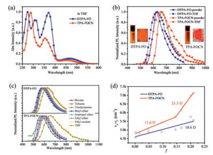
To better understand excited-state character, the UV-vis absorption and PL spectra of two compounds were recorded in various solvents ranging from nonpolar n-hexane to polar THF (Fig. 1c and Fig. S2 in Supporting information). The detailed photophysical data were summarized in Tables S2 and S3 (Supporting information). The absorption spectra of DTPA-FO and TPA-FOCN seldom changed in terms of their shapes and positions with increasing solvent polarity, implying a rather small dipole change at ground state in different solvents. The fluorescence measurements reveal the remarkably red-shifted and broadened spectra as solvent polarity increases. The large solvatochromic effect indicates a strong ICT-character excited state of these two compounds. Interestingly, TPA-FOCN displays less red-shifted emission than DTPA-FO in low-polarity solvents from n-hexane to butyl ether, while it shows more red-shifted emission in medium-polarity solvents from isopropyl ether to THF. Eventually, a much larger redshift of TPA-FOCN is observed. The Lippert-Mataga relation was applied to better understand the solvent effect in a plot of the Stokes shift versus solvent polarizability (∆), as shown in Fig. 1d. Notably, DTPA-FO is fitted into a straight line while TPA-FOCN possesses two sets of linear relationships. From the slope of the line, the dipole moment of excited state, μe, is calculated to be only 10.6 D for DTPA-FO. As a comparison, TPA-FOCN possesses the μe of 11.6 D in low-polarity solvents and 21.3 D in high-polarity solvents respectively, corresponding to two different excited states: less ICT-like state for low-polarity solvents and more ICT-like state for high-polarity solvents. In high-polarity solvents, the μe is very close to that of a typical ICT-state molecule in (N, N-dimethylamino)benzonitrile (DMABN, μe = 23 D) [32], demonstrating a strong ICT-state character of TPA-FOCN. Here, the μe of 10.6 D and 11.6 D can be ascribed to hybridized local and charge-transfer (HLCT) excited state [33-41]. For the ηPL in solutions from hexane to THF, both compounds show the decreasing trend due to increasing ICT component as solvent polarity increases, from 27.94% to 3.89% for DTPA-FO and 29.37% to 2.11% for TPA-FOCN, respectively (Table S4 in Supporting information). Furthermore, the photophysical properties of DTPA-FO and TPA-FOCN were measured in powder and spin-coating film, respectively (Table 1, Fig. 1b, Figs. S3 and S4 in Supporting information). Compared with the orange emission of TPA-FO in solids [31], TPA-FOCN exhibits the deep-red emission feature under two different types of solid states (668 nm for powder and 656 nm for film). Though the emission wavelength of TPA-FOCN is more red-shifted relative to DTPA-FO, the ηPL (10%) can be well maintained in powder. What is more, the ηPL of TPAFOCN is higher than that of DTPA-FO in spin-coating film. Both can be ascribed to the suppression of non-radiative deactivation upon the incorporation of cyano group [42]. As a comparison, the introduction of cyanophenyl as acceptor is the more effective way to achieve the deep-red materials relative to that by incorporation of extra donors.
 DownLoad:
CSV
DownLoad:
CSV
 |
To reveal the origin of largely red-shifted emission of TPA-FOCN relative to that of DTPA-FO, a theoretical calculation was carried out in TPA-FOCN and DTPA-FO (Fig. 2a). In terms of the frontier molecular orbital (HOMO and LUMO), LUMO is mostly localized on the FO unit, while HOMO is distributed on the whole molecular backbone of DTPA-FO. From DTPA-FO to TPA-FOCN, one-sided TPA unit is replaced by cyanophenyl, resulting in a great change of the wavefunctions of HOMO and LUMO. HOMO of TPA-FOCN is mostly localized on TPA and partial phenyl ring of FO, while its LUMO is mainly distributed on FO unit and cyanophenyl. As a result, a large orbital separation between HOMO and LUMO is observed for TPAFOCN, indicative of a stronger ICT character in TPA-FOCN.
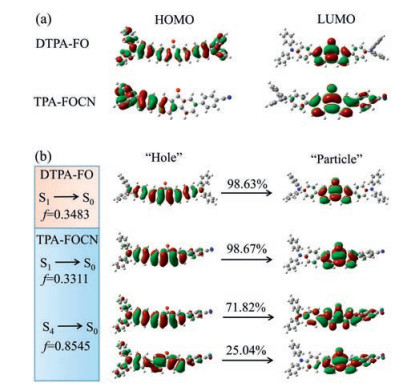
To describe the excited-state character of TPA-FOCN and DTPA-FO, NTOs of excited state are further calculated at the excited state S1 geometry (Fig. 2b and Figs. S8 and S9 in Supporting information). The estimated emission wavelengths of TPA-FOCN and DTPA-FO are in good agreement with the results in n-hexane solvent. The "particle" of TPA-FOCN is mainly localized on FO unit, which is similar to that of DTPA-FO. The "hole" of TPA-FOCN is distributed on TPA unit and FO unit, but it is on the whole molecular backbone for DTPA-FO. So HLCT state that consists of ICT (TPA→FO) and LE of FO is mainly responsible for the emission of TPA-FOCN in low-polarity solvents, and cyano group does not participate in "particle" according to results. Thus, the more localized "hole" results in the blue-shifted emission of TPA-FOCN in contrast to that of DTPA-FO in hexane. With the increase of solvent polarity, TPA-FOCN shows a stronger ICT character relative to DTPA-FO, probably because the high-lying ICT state (such as S4) with main participation of cyano group can be stabilized to become the low-lying excited state.
Cyclic voltammetry (CV) curves of TPA-FOCN and DTPA-FO were measured against the ferrocene/ferrocenium redox couple as reference (Table 1 and Fig. S5 in Supporting information). The LUMO level of TPA-FOCN is -3.31 eV, which is lower than that of DTPA-FO (-3.19 eV). Meanwhile, the HOMO level of TPA-FOCN is -5.21 eV which is almost the same as -5.20 eV of DTPA-FO. As a consequence, TPA-FOCN possesses much narrower electronic bandgap of 1.90 eV in comparison with 2.01 eV of DTPA-FO, corresponding to the more red-shifted emission of TPA-FOCN than DTPA-FO in medium- and high-polarity solvents.
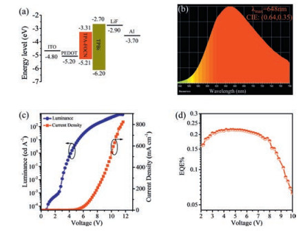
To explore the application of deep-red TPA-FOCN, we focused on its electroluminescent (EL) properties. In view of its suitable energy levels and good solubility, non-doped solution-processed OLED was fabricated with a multilayer device structure (Fig. 3a): ITO/PEDOT-PSS (40 nm)/TPA-FOCN (50 nm) /TPBi (40 nm)/LiF (1 nm)/Al (100 nm). Where, PEDOT-PSS is poly(3, 4-ethylenedioxy-thiophene)-polystyrene sulfonate, serving as the holeinjecting layer. TPBi is 1, 3, 5-tris(1-phenyl-1H-benzimidazol-2-yl) benzene, acting as electron-transporting and hole-blocking layer. LiF is used as electron-injecting material in this device. Deep-red emission was obtained with EL spectrum peaked at 648 nm in device, together with CIE coordinate of (0.64, 0.35). The EL spectrum (Fig. 3b) of TPA-FOCN device well accords with its corresponding PL spectrum. The turn-on voltage of the device is 4.0 V, which is recorded at the luminance of 1 cd/m2, and the maximum luminance can reach 824 cd/m2 (Fig. 3c). TPA-FOCN device showed a maximum luminous efficiency of 0.13 cd/A and a maximum external quantum efficiency (EQE) of 0.22% (Figs. 3c and d). Though EQE of this OLED is not very high, it is a meaningful attempt for non-doped solution-processed deep-red OLED.
In summary, we constructed a new D-A molecule TPA-FOCN by modifying DTPA-FO with the distinctive cyanophenyl group, which shows deep-red emission at 668 nm in powder. As an ancillary acceptor, the incorporation of cyanophenyl not only enhances the ability of acceptor, but also modulates the ICT components in emissive state. Compared with DTPA-FO, the strong ICT character of TPA-FOCN has been further confirmed by experimental and theoretical investigations. Importantly, the introduction of cyanophenyl maintains high PL efficiency of 10%. Our results suggest that cyanophenyl can act as an ancillary acceptor to effectively decrease emission band-gap, increase ICT component and maintain high PL efficiency, which is a good building block to design high-efficiency narrow-band-gap fluorescent materials using D-A molecular architecture.
This work is supported by the National Natural Science Foundation of China (Nos. 91833304, 51873077, 51803071 and 51673083), the National Basic Research Program of China (Nos. 2015CB655003 and 2016YFB0401001), the Postdoctoral Innovation Talent Support Project (Nos. BX201700097 and BX20180121), the China Postdoctoral Science Foundation (Nos. 2017M620108 and 2018M641767) and JLUSTIRT (No. 2019TD-33).
Supplementary material related to this article can be found, in the online version, at doi:https://doi.org/10.1016/j.cclet.2019.07.059.
L. Yao, S. Zhang, R. Wang, et al., Angew. Chem. Int. Ed. 53(2014) 2119-2123. doi: 10.1002/anie.201308486
W. Li, Y. Pan, R. Xiao, et al., Adv. Funct. Mater. 24(2014) 1609-1614. doi: 10.1002/adfm.201301750
S. Wang, X. Yan, Z. Cheng, et al., Angew. Chem. Int. Ed. 54(2015) 13068-13072. doi: 10.1002/anie.201506687
Y. Zhang, Y. Wang, J. Song, et al., Adv. Opt. Mater. 6(2018) 1800466. doi: 10.1002/adom.201800466
J. Xue, C. Li, L. Xin, L. Duan, J. Qiao, Chem. Sci. 7(2016) 2888-2895. doi: 10.1039/C5SC04685H
Y. Yuan, Y. Hu, Y.X. Zhang, et al., Adv. Funct. Mater. 27(2017) 1700986. doi: 10.1002/adfm.201700986
K.T. Ly, R.W. Chen-Cheng, H.W. Lin, et al., Nat. Photonics 11(2016) 63-68.
I. Garcia-Moreno, A. Costela, V. Martin, M. Pintado-Sierra, R. Sastre, Adv. Funct. Mater. 19(2009) 2547-2552. doi: 10.1002/adfm.200900112
W. Qin, K. Li, G. Feng, et al., Adv. Funct. Mater. 24(2014) 635-643. doi: 10.1002/adfm.201302114
J. Zhang, R. Chen, Z. Zhu, et al., ACS Appl. Mater. Interfaces 7(2015) 26266-26274. doi: 10.1021/acsami.5b08539
J.V. Caspar, E.M. Kober, B.P. Sullivan, T.J. Meyer, J. Am. Chem. Soc. 104(1982) 630-632. doi: 10.1021/ja00366a051
S.D. Cummings, R. Eisenberg, J. Am. Chem. Soc. 118(1996) 1949-1960. doi: 10.1021/ja951345y
C.T. Chen, Chem. Mater. 16(2004) 4389-4400. doi: 10.1021/cm049679m
K.R. Graham, Y. Yang, J.R. Sommer, et al., Chem. Mater. 23(2011) 5305-5312. doi: 10.1021/cm202242x
K.R.J. Thomas, J.T. Lin, M. Velusamy, Y.T. Tao, C.H. Chuen, Adv. Funct. Mater. 14(2004) 83-90. doi: 10.1002/adfm.200304486
M. Shimizu, R. Kaki, Y. Takeda, et al., Angew. Chem. Int. Ed. 51(2012) 4095-4099. doi: 10.1002/anie.201108943
Q. Zhang, H. Kuwabara, W.J. Potscavage Jr., et al., J. Am. Chem. Soc. 136(2014) 18070-18081. doi: 10.1021/ja510144h
X. Han, Q. Bai, L. Yao, et al., Adv. Funct. Mater. 25(2015) 7521-7529. doi: 10.1002/adfm.201503344
Y. Zhang, D. Zhang, M. Cai, et al., Nanotechnology 27(2016) 094001. doi: 10.1088/0957-4484/27/9/094001
S. Wang, Z. Cheng, X. Song, et al., ACS Appl. Mater. Interfaces 9(2017) 9892-9901. doi: 10.1021/acsami.6b14796
X.O. Gong, P.K. Iyer, D. Moses, et al., Adv. Funct. Mater. 13(2003) 325-330. doi: 10.1002/adfm.200304279
W. Porzio, S. Destri, U. Giovanella, et al., Thin Solid Films 492(2005) 212-220. doi: 10.1016/j.tsf.2005.06.041
W. Porzio, S. Destri, M. Pasini, et al., Synth. Met. 159(2009) 513-517. doi: 10.1016/j.synthmet.2008.11.017
P. Sonar, T.J. Ha, A. Dodabalapur, Chem. Commun. 49(2013) 1588-1590. doi: 10.1039/C2CC37131F
L.F. Lai, C. Qin, C.H. Chui, et al., Dyes Pigments 98(2013) 428-436. doi: 10.1016/j.dyepig.2013.03.007
L.C. Chi, H.F. Chen, W.Y. Hung, et al., Sol. Energy Mater. Sol. Cells 109(2013) 33-39. doi: 10.1016/j.solmat.2012.10.019
A.L. Capodilupo, V. Vergaro, E. Fabiano, et al., J. Mater. Chem. B 3(2015) 3315-3323. doi: 10.1039/C4TB02116A
A.L. Capodilupo, V. Vergaro, G. Accorsi, et al., Tetrahedron 72(2016) 2920-2928. doi: 10.1016/j.tet.2016.04.012
Y. Duan, C. Ju, G. Yang, et al., Adv. Funct. Mater. 26(2016) 8968-8977. doi: 10.1002/adfm.201602765
E. Zojer, A. Pogantsch, E. Hennebicq, et al., J. Chem. Phys. 117(2002) 6794-6802. doi: 10.1063/1.1507106
Y. Liu, X. Tao, F. Wang, et al., J. Phys. Chem. C 112(2008) 3975-3981. doi: 10.1021/jp7117373
Z.R. Grabowski, K. Rotkiewicz, W. Rettig, Chem. Rev. 103(2003) 3899-4031. doi: 10.1021/cr940745l
C. Wang, X.L. Li, Y. Gao, et al., Adv. Opt. Mater. 5(2017) 1700441. doi: 10.1002/adom.201700441
T. Liu, L. Zhu, C. Zhong, et al., Adv. Funct. Mater. 27(2017) 1606384. doi: 10.1002/adfm.201606384
X. Tang, X.L. Li, H. Liu, et al., Dyes Pigments 149(2018) 430-436. doi: 10.1016/j.dyepig.2017.10.033
Y. Gao, S. Zhang, Y. Pan, et al., Phys. Chem. Chem. Phys. 18(2016) 24176-24184. doi: 10.1039/C6CP02778D
W. Li, Y. Pan, L. Yao, et al., Adv. Opt. Mater. 2(2014) 892-901. doi: 10.1002/adom.201400154
Y. Pan, W. Li, S. Zhang, et al., Adv. Opt. Mater. 2(2014) 510-515. doi: 10.1002/adom.201300467
S. Zhang, W. Li, L. Yao, et al., Chem. Commun. 49(2013) 11302-11304. doi: 10.1039/c3cc47130f
S. Zhang, L. Yao, Q. Peng, et al., Adv. Funct. Mater. 25(2015) 1755-1762. doi: 10.1002/adfm.201404260
C. Zhou, D. Cong, Y. Gao, et al., J. Phys. Chem. C 122(2018) 18376-18382. doi: 10.1021/acs.jpcc.8b07083
H. Uoyama, K. Goushi, K. Shizu, H. Nomura, C. Adachi, Nature 492(2012) 234-240. doi: 10.1038/nature11687

Figure 1 (a) UV-vis spectra of DTPA-FO and TPA-FOCN in diluted THF solutions. (b) The PL spectra of DTPA-FO (λex = 440 nm) and TPA-FOCN (λex = 445 nm) in diluted THF solution and solid state. (c) Solvatochromic PL spectra of DTPA-FO (λex = 440 nm) and TPA-FOCN (λex = 430 nm) with increasing polarity of solvents. (d) Linear fitting of Lippert-Mataga model (the open squares and circles represent the Stokes shifts in different solvents, and the lines are fitted for solvatochromic models of the two compounds).

Figure 2 (a) Molecular orbital diagrams of HOMO and LUMO of optimized DTPA-FO and TPA-FOCN. (b) NTO in DTPA-FO and TPA-FOCN. Herein, f represents for the oscillator strength, and the percentage weights of hole-particle are given based on the S1 state geometry.

Figure 3 (a) Schematic energy level diagram of TPA-FOCN device. (b) EL spectrum of a multilayer OLED based on TPA-FOCN as the emitter. (c) Luminance-voltage-current density curves of TPA-FOCN. (d) External quantum efficiency-voltage curve of TPA-FOCN.

 扫一扫看文章

扫一扫关注我们

 下载:
下载:
 下载:
下载: