Citation:
Yuan Hong, Kong Long, Li Tao, Zhang Qiang. A review of transition metal chalcogenide/graphene nanocomposites for energy storage and conversion[J]. Chinese Chemical Letters,
2017, 28(12): 2180-2194.
doi:
10.1016/j.cclet.2017.11.038
A review of transition metal chalcogenide/graphene nanocomposites for energy storage and conversion
作者简介:Hong Yuan receieved his B.S. degree from Yanbian University in 2011. He received his Ph.D. degree from Beijing Institute of Technology in 2017. After that, he joined in Prof. Qiang Zhang's research group as a postdoctoral researcher at the Department of Chemical Engineering in Tsinghua University. His research interests are focused on the design and synthesis of nanostructured materials for Li-S batteries, Li-ion batteries and dyesensitized solar cells; Long Kong received his B.S. and M.S. from School of Metallurgical Science and Engineering, Central South University in 2010 and 2013, respectively. He then obtained his Ph.D. from Department of Chemical Engineering, Tokyo Institute of Technology (Japan) in 2016. He joined in Prof. Qiang Zhang's research group in October, 2016, studying the topics of rational design of Li-S batteries. He is now interested in synthesis of nanomaterials and their applications in Li-ion/Li-S batteries; Tao Li received his B.S. and Ph.D. from School of Metallurgical Science and Engineering, Central South University in 2012 and 2017, respectively. He joined in Prof. Qiang Zhang's research group in September, 2017, studying the topics of rational design of lithium metal batteries. He is now interested in synthesis of nanomaterials and their applications in Li-based batteries; Qiang Zhang received his bachelor and Ph.D. degree from Tsinghua University in 2004 and 2009, respectively. After a stay in Case Western Reserve University, U.S.A., and Fritz Haber Institute of the Max Planck Society, Germany, he joined in Tsinghua University at 2011. He held the Newton Advanced Fellowship from Royal Society, U.K. and the NSFC Young Scholar in China. His current research interests are advanced energy materials, including lithium metal anode, lithium sulfur batteries, and electrocatalysis. His citation is over 13000 times and his h-index is 61 now;
Beijing Key Laboratory of Green Chemical Reaction Engineering and Technology, Department of Chemical Engineering, Tsinghua University, Beijing 100084, China
Author Bio:Hong Yuan receieved his B.S. degree from Yanbian University in 2011. He received his Ph.D. degree from Beijing Institute of Technology in 2017. After that, he joined in Prof. Qiang Zhang's research group as a postdoctoral researcher at the Department of Chemical Engineering in Tsinghua University. His research interests are focused on the design and synthesis of nanostructured materials for Li-S batteries, Li-ion batteries and dyesensitized solar cells;Long Kong received his B.S. and M.S. from School of Metallurgical Science and Engineering, Central South University in 2010 and 2013, respectively. He then obtained his Ph.D. from Department of Chemical Engineering, Tokyo Institute of Technology (Japan) in 2016. He joined in Prof. Qiang Zhang's research group in October, 2016, studying the topics of rational design of Li-S batteries. He is now interested in synthesis of nanomaterials and their applications in Li-ion/Li-S batteries;Tao Li received his B.S. and Ph.D. from School of Metallurgical Science and Engineering, Central South University in 2012 and 2017, respectively. He joined in Prof. Qiang Zhang's research group in September, 2017, studying the topics of rational design of lithium metal batteries. He is now interested in synthesis of nanomaterials and their applications in Li-based batteries;Qiang Zhang received his bachelor and Ph.D. degree from Tsinghua University in 2004 and 2009, respectively. After a stay in Case Western Reserve University, U.S.A., and Fritz Haber Institute of the Max Planck Society, Germany, he joined in Tsinghua University at 2011. He held the Newton Advanced Fellowship from Royal Society, U.K. and the NSFC Young Scholar in China. His current research interests are advanced energy materials, including lithium metal anode, lithium sulfur batteries, and electrocatalysis. His citation is over 13000 times and his h-index is 61 now;
Received Date:
09 November 2017 Accepted Date:
27 November 2017 Revised Date:
27 November 2017 Available Online:
01 December 2017
Abstract:
To meet the ever-increasing energy demands, advanced electrode materials are strongly requested for the exploration of advanced energy storage and conversion technologies, such as Li-ion batteries, Li-S batteries, Li-/Zn-air batteries, supercapacitors, dye-sensitized solar cells, and other electrocatalysis process (e.g., oxygen reduction/evolution reaction, hydrogen evolution reaction). Transition metal chalcogenides (TMCs, i.e., sulfides and selenides) are forcefully considered as an emerging candidate, owing to their unique physical and chemical properties. Moreover, the integration of TMCs with conductive graphene host has enabled the significant improvement of electrochemical performance of devices. In this review, the recent research progress on TMC/graphene composites for applications in energy storage and conversion devices is summarized. The preparation process of TMC/graphene nanocomposites is also included. In order to promote an in-depth understanding of performance improvement for TMC/graphene materials, the operating principle of various devices and technologies are briefly presented. Finally, the perspectives are given on the design and construction of advanced electrode materials.
With the development of human society and economy, aggravating energy crisis as well as accompanying environmental degradation and ecological destruction become seriously threats for sustainable society [1-4]. Therefore, the exploration of clean and renewable energy is becoming a global spotlight. Considerable efforts have been devoted to exploit renewable energy, such as solar energy, wind energy, geothermal energy, and so on. This can alleviate the reliance on consumption of fossil fuels. However, fully realizing the utilization of the intermittent renewable energy sources strongly relies on advanced energy storage and conversion technologies [2, 5-7]. The electrochemical rechargeable batteries (lithium-ion batteries (LIBs), lithium-sulfur batteries (LSBs), lithium-air batteries, zinc-air batteries, etc.), supercapacitors, solar cells and other electrocatalysis process (e.g., oxygen reduction/ evolution reaction (ORR/OER), hydrogen evolution reaction (HER)) have gained the increasing exploration [8, 9]. Although excellent researches in the fields of energy storage and conversion have flourished around the world, the exploitation of high-efficiency electrode materials, electrocatalysts and photocatalysts need to be further propelled [10].
Over the past decades, transition metal chalcogenides (TMCs, mainly sulfides and selenides) have received ever-growing research interests as potential electrode materials for energy storage and conversion due to its tunable stoichiometric compositions, unique crystal structures, and rich redox sites, as well as relatively higher electrical conductivity in comparison to their transition metal oxide counterparts [11-13]. For instance, in comparison to routine anode materials (graphite) in LIBs based on insertion/deinsertion mechanism, the TMCs generally possess higher theoretical special capacity [11, 14], which can be mainly attributed to the conversional mechanism that can be described as MS(Se)n + 2nLi+ + 2ne- ↔ nLi2S(Se) + M [12, 15, 16]. Moreover, the lithiation processes containing additional alloying reactions (M = Sn, In, Sb, and Bi) [17-19] or insertion procedure (layered structure, M = Mo, W, and V) [20-22] could further contribute to electrode capacity in some cases. When applied in LSBs, nanostructured TMCs as polar hosts can afford stronger affinity with soluble polysulfides that generally leads to the serious "shuttle effect", due to polar sulfiphilic surface of TMCs, rendering the LSBs with higher sulfur utilization and long cycling life [23]. Benefited from the reversible redox reaction of TMCs in alkaline medium (MS(Se) + OH- ↔ MS(Se)OH + e-), supercapacitors with TMC electrodes also demonstrate excellent energy density [11]. With regards to metal-air batteries, TMCs served as active materials of air electrode have been demonstrated excellent electrocatalytic performance for ORR and OER, similar to those of precious catalysts [24]. As for dye-sensitized solar cells (DSSCs) which is an important type of energy conversion devices, the TMCs used as counter electrodes generally deliver superior energy conversion efficiency to the cells with Pt electrode. Water splitting derived by electro-and photoelectron-chemistry is considered as a promising pathway for hydrogen production. Similar to the application in metal-air batteries, TMCs served as a kind of important photo-/electro-catalyst to catalyze water dissociation also exhibit comparable catalytic reactivity for those of precious catalysts, owing to their semiconducting characteristics, special band structure as well unique electronic configuration [25]. However, the challenges of the low special surface area, inferior reactivity, low electron/ion transfer rate, and rapid recombination rate of electrons and holes [26], remain for the practical applications of TMCs in energy devices.
Graphene as a two-dimensional honeycomb sp2-hybridized carbon nanosheets with single atom thickness, has drawn tremendous attentions in energy research field due to its unique physicochemical properties since it was firstly investigated by Andre Geim and co-workers in 2004 [27]. Theoretical research indicates that ideal graphene can offer an ultrahigh special surface area of 2600 m2/g [28, 29], which is much higher than that of conventional graphite power (10 m2/g) and carbon black (900 m2/g) [30]. In addition, high electrical conductivity, mechanical strength and flexible, and charge carrier mobility also endow graphene with a huge potential in electrode materials for next-generation energy storage and conversion [31-42]. With the development of graphene technologies in photo-and electrochemical researches, graphene-based nanostructured materials have been investigated extensively on account of two dimensional thin sheet structure of graphene that makes it as an ideal support for the growth of inorganic nanomaterials [43-45]. A recent review has appeared on the synthetic routes for preparing hybrid graphene-based nanomaterials for cutting-edge energy storage and conversion applications (Fig. 1) [46]. Graphene can serve as matrix to inhibit the self-aggregation of inorganic materials, providing abundant pores to promote the mass transfer and interconnected electronic conductive pathways to facilitate electron transfer [35]. Hence, a marvelously enhanced properties stemmed from both individual counterparts have been endowed by graphene-based materials, which can effectively conquer the weaknesses of independent components [47]. Therefore, the composites of TMCs and graphene can be considered as efficient electrode active materials for advanced energy storage and conversion.
图 1
图 1
Typical synthetic pathways for preparing graphene-based nanocomposite materials for energy storage and conversion applications. Reproduced with permission [46]. Copyright 2015, Nature Publishing Group.
Figure 1.
Typical synthetic pathways for preparing graphene-based nanocomposite materials for energy storage and conversion applications. Reproduced with permission [46]. Copyright 2015, Nature Publishing Group.
In this review, recent advances in the typical TMC/graphene electrode materials for energy storage and conversion applications containing LIBs, LSBs, metal-air battery, OER, ORR, supercapacitors, DSSCs, and HER, are included. The material structures and synthetic methods of TMCs/graphene are summarized and their electrochemical performances in different energy applications are highlighted. The general design principles on electrode materials for future energy devices are also presented.
2.
TMC/graphene composites in energy storage
2.1
Li-ion batteries
Since their commercialization by Sony Corporation in the 1990s, rechargeable LIBs have dominated the consumer market of personal smart electronics devices over 20 years, and are expected to be employed inelectric vehicles (EVs) and hybrid electric vehicles (HEVs) [21, 48-53]. To meet these requirements, considerable efforts have been devoted to enhancing all-around performances of the state-of-the-art rechargeable LIBs. Typical LIBs composed of anode (e.g., graphite), cathode (e.g., LiCoO2), electrolyte, and separator. The charge and discharge mechanism of LIBs is based on the rocking-chair concept (Fig. 2) [54]. During charging, the Li ions desert from the metal oxides, migrate to anode across the electrolyte, and subsequently, insert into the layers of graphite anode. Conversely, the Li ions can spontaneously deintercalate from the anode and transfer to the oxide cathode during discharging if an external circuit presents between the anode and cathode. Therefore, with the continual migration of Li ions, electrons transfer to cathode through the external circuit, thus continuously affording power output for electronic equipment at external circuit [55, 56]. Obviously, the electrochemical performance of LIBs strongly depend on the lithium storage properties of anode [55]. Although graphite is the commonly used anode material in commercial LIBs, the relative low charge capacity (372 mAh/g) is not satisfied with the development of LIBs [57-60]. In order to enhance the energy/power densities of LIBs, the new anode materials with excellent lithium storage properties and rapid lithiation/delithiation rate are required.
图 2
图 2
Schematic diagram of a typical Li-ion (LiCoO2-graphite) cell. Reproduced with permission [54]. Copyright 2013, American Chemical Society.
Figure 2.
Schematic diagram of a typical Li-ion (LiCoO2-graphite) cell. Reproduced with permission [54]. Copyright 2013, American Chemical Society.
Recently, the hybrids of metal chalcogenides and graphene have attracted intense attention in LIBs [61]. The presence of metal chalcogenides with high theoretical specific capacity can enhance the lithium storage performances [62-64], while graphene matrix with express electronic conductivity can benefit electrochemical kinetics [65-68]. Moreover, graphene as supporting matrix remarkably restrains the severe pulverization of active materials during continuous lithiation/delithiation process [61].
In general, the conversion reaction of metal sulfides (e.g., CoS, NiS) with Li ions can contribute a high lithium storage. Moreover, the incorporation of metal sulfides with graphene enables facile electron transfer. Xie et al. have successfully prepared a CoS2/ graphene (CoS2/G) nanocomposite by a facile one-pot hydrothermal reaction using graphene oxide (GO), thioacetamide, and cobalt chloride hexahydrate as the starting materials [69]. Based on the effective integration of CoS2 and graphene, enhanced Li-storage properties were delivered. Subsequently, a series of Co3S4/ grapheme [70], CoS/grapheme [71], CoS2/graphene [72] were employed as anode materials in LIBs, exhibiting a high discharge capacity and excellent cycling stability. Similarly, Mahmood et al. described a one-pot hydrothermal approach followed by annealing for preparing nickel sulfides (Ni3S4 and NiS1.03)/nitrogen-doped graphene (NG) sheets composites [73], exhibiting high reversible performance. In order to settle the electron/ion transport issues in the large metal sulfides crystal and eliminate the strain induced by volume variety during cycling, Wu and co-workers demonstrated zero-dimensional (0D) metal sulfides (CoS, NiS, MnS)/onedimensional (1D) porous carbon nanowires/three-dimensional (3D) graphene network nanocomposites with unique multiscale, multidimensional, and hierarchically ordered architecture [74]. This hierarchically hybrid structure ensured the greatly enhanced electron/ion transport kinetics, mitigated the volume expansion of metal sulfides during lithiation/delithiation cycle, and maintained the robust mechanical stability of electrode, thus imparting excellent reversible capacity, cycling, and rate performances.
Layered metal sulfides (e.g., MoS2, WS2) have appealed dramatic interests for applications in LIBs since the additional electrochemical contributions to Li storage derived from intercalation process of layered structure [75]. However, their intrinsically low conductivity seriously hinders the facile electron/ion transport, leading to a fast capacity degradation [76]. Teng et al. designed an interesting nanostructure that is vertical MoS2 nanosheets array in situ grown on graphene sheets (MoS2/G) via a simple hydrothermal route, manifesting a stable cycling stability over 400 cycles [77]. Although the integration of graphene effectively enhanced the global conductivity of MoS2/G anode, the diffusion of electrolyte remained to be improved. Wang et al. reported a honeycomb-like MoS2 anchored on 3D grapheme (3DG) foam (HC-MoS2@GF) [78]. Due to the improved electron/ion transport of 3DG foam and high electrochemical activity of ultrathin honeycomb-like MoS2 architecture, HC-MoS2@GF displayed remarkable reversible capacity of 1235.3 mAh/g at 200 mA/g, excellent rate performance, and cycling stability. Shan et al. also delivered a scalable freestanding ultrathin film combining honeycomb-like MoS2 sheets with nitrogen-doped graphene, forming a unique hierarchical film-foam-film (3F) topdown architecture from the macro-to the micro-and the nanoscale through a hydrothermal reaction coupled with hydrazine vapor reduction [79]. This special hierarchical 3F structure provided sufficient porous and interconnect channels for Li+ diffusion. The layer-by-layer structure also significantly buffered the electrode destruction resulted from the expansion of anode on cycling. Aligned nanostructures afford order channels for ion diffusions during electrochemical energy storage [80].
In order to further facilitate the ion/electron transport in anode, a hybrid 3D nanoarchitecture WS2 nanosheets/carbon nanotubereduced graphene oxide (WS2/CNT-rGO) aerogel with ordered microchannel structure was successfully synthesized by a facile solvothermal method coupled with ice-template assisted freeze drying technology and post annealing process (Fig. 3) [81]. Benefited from superior electron transfers of CNTs and rapid ionic permeation of 3D structure, as well as the layered structure of WS2, WS2/CNT-rGO hybrid exhibited enhanced electrochemical performance in LIBs, delivering a specific capacity of 749 mAh/g at 100 mA/g.
图 3
图 3
(a) Schematic illustration of the synthesis process of WS2/CNT-rGO aerogel with 3D ordered microchannel nanoarchitecture. (b) SEM image of CNT-rGO aerogel with 3D ordered structure. (c) SEM image of WS2/CNT-rGO-200 aerogel prepared with 200 mg (NH4)2WS4 precursor. Reproduced with permission [81]. Copyright 2016, Wiley VCH.
Figure 3.
(a) Schematic illustration of the synthesis process of WS2/CNT-rGO aerogel with 3D ordered microchannel nanoarchitecture. (b) SEM image of CNT-rGO aerogel with 3D ordered structure. (c) SEM image of WS2/CNT-rGO-200 aerogel prepared with 200 mg (NH4)2WS4 precursor. Reproduced with permission [81]. Copyright 2016, Wiley VCH.
SnS2, due to its extra alloying in Li storage process, have been emerged as a promising alternative for LIBs anode [82]. The high initial discharge capacity has been demonstrated, the cycling durability still remain challenges. Chang et al. prepared few-layer SnS2 nanosheets/graphene nanocomposites by hydrothermal method [83]. The impressive hybrid structure eliminated the stress damage of anode upon cycling and promoted the synergistically enhanced electrochemical performance, thus displaying a high specific capacity of more over 920 mAh/g. However, the commonly low-yield production of SnS2/graphene, originated from the complicated and rigorous process, are unfavorable for their practical applications in LIBs. Very recently, Zheng et al. described the fabrication of flexible SnS2/sulfur-doped reduced graphene oxide (S-rGO) composite via a reliable dissolutionreprecipitation pathway [84]. The SnS2 nanocrystals with the primary grain size of ca. 4 nm were uniformly anchored on the rGO sheets, significantly suppressing the breaking and the shedding of SnS2 from the rGO nanosheets. As a consequence, the SnS2/S-rGO composite delivered a high discharge capacity of 1078 mAh/g at 0.1 A/g, long cycle life, and excellent rate performance.
Metal selenides are another important class of candidate for anode of LIBs. In order to understand the electrochemical Listorage mechanisms and electrochemical performance of lead selenide (PbSe), Xie et al. employed in situ transmission electron microscopy (TEM) technique for observing the structural and phase evolutions of PbSe nanocrystals implemented by supporting it on few-layered rGO films [85]. They demonstrated that rGO played a critical role in increasing the whole conductivity of anode, thus elevating the electrochemical performance of rGO/PbSe. In 2015, Li et al. reported a reduced graphene oxide/cobalt selenide (rGO/CoSe2) composite as a promising anode material for LIBs for the first time [86]. Benefiting from the electrical conductivity of rGO as well as its toleration for the anode structure degradation during cycling, the rGO/CoSe2 composite delivered a high reversible capacity of 1577 mAh/g at 200 mA/g after 200 cycles. Recently, ZnSe/rGO [87], MoSe2/graphene [88] and Bi2Se3/ graphene [89] have also reported as a promising anode materials in LIBs, confirming an enhanced electrochemical performance to a certain extent compared with individual selenides.
2.2
Li-S batteries
To meet the requirement of high energy/power density batteries for energy markets, rechargeable Li-S batteries have attracted unprecedented attention due to its high theoretical specific capacity (1675 mAh/g) and a theoretical energy density (2600 Wh/kg) [90-92]. This is stemmed from reversibly multielectro electrochemical reaction between S and Li: 16Li + S8→8 Li2S (Fig. 4a) [93-97]. In addition, the elemental S is low cost, earth rich, and environmental friendly, which endows the Li-S batteries with more suitability in high-end applications (e.g., EVs and HEVs) [98-100]. Generally, a typical Li-S battery commonly composes of four main components: S/C composite cathode, organic electrolyte, separator and Li metal anode.
A widely accepted mechanism about the complete reduction of element S contains following stages: S8 ↔ Li2S8 ↔ Li2S6 ↔ Li2S4 ↔ Li2S2 ↔ Li2S [101]. There are two plateaus in charge/discharge profiles (Fig. 4b), in which the upper voltage plateau is related to the solid-liquid conversion of elemental S to lithium polysulfides (Li2Sn, 4≤n≤8), while the lower discharge plateau is assigned to the liquid-solid transformation of Li2Sn to Li2S2/Li2S [23, 102]. However, the shuttle effect, which is the dissolution of soluble lithium polysulfide intermediates (Li2Sn, 4≤n≤8) into electrolyte and their subsequent migration between anode and cathode region, can induce the corrosion of Li metal and loss of cathode active S, leading to the rapid declining in discharge capacity and cycle life [103, 104]. The intrinsic insulating properties of elemental S and the final discharge products (Li2S2/Li2S) also result in the sluggish reaction kinetics. Besides, the huge volume expands/ shrinkage (up to 80%) originated from the conversion of elemental S to Li2S also need to be confronted, which usually lead to the collapse of electrode structure [105, 106]. Therefore, the rational design of nanostructured conductive polar sulfur hosts, which is desired to mitigate the diffusion of polysulfides through the physical cavity confine or chemical covalence adsorption, is a promising strategy to flourish Li-S batteries [107-111]. The nanostructured carbonaceous material [101, 112-119], nanostructured transition metal compounds [23], and their compounds [120, 121] have been demonstrated as an effective host for Li-S batteries. Considering that some published articles have reviewed on carbon material [122-124] and nanostructured transition metal compounds [23, 125], hence, main concern in this part is paid to the composites of TMCs and graphene.
图 4
图 4
(a) Schematic of a typical Li-S battery and energy densities of various rechargeable battery systems. Reproduced with permission [93]. Copyright 2017, Wiley VCH. (b) A typical charge-discharge curve with different sulfur-containing intermediates at different stages (the inset illustrates the shuttling process of polysulfides). Reproduced with permission [23]. Copyright 2017, Wiley VCH.
Figure 4.
(a) Schematic of a typical Li-S battery and energy densities of various rechargeable battery systems. Reproduced with permission [93]. Copyright 2017, Wiley VCH. (b) A typical charge-discharge curve with different sulfur-containing intermediates at different stages (the inset illustrates the shuttling process of polysulfides). Reproduced with permission [23]. Copyright 2017, Wiley VCH.
Recently, to address the challenges of the poor affinity of nonpolar surface of carbon materials to polar sulfur species, Peng et al. proposed a promising approach that is to adopt polar "sulfiphilic" surface chemistry to entrap lithium (poly)sulfides (Fig. 5a) [107]. Inspired by digging canals and widening/deepening existing channels for taming the flood in common life, Yuan et al. proposed a conductive sulfiphilic host material composed of polar CoS2 supported on graphene for significantly accelerating the redox kinetics of lithium polysulfides [121]. Semi-metallic property of CoS2 and high electrical conductivity of graphene significantly accelerated the electron transfer. Moreover, the sulfiphilic surface of CoS2 offered strong chemical interplay to polar sulfide species, which remarkably captured the soluble polysulfides and suppressed their diffusion into anode region. Besides, CoS2 also affords additional redox activities, effectively impelling the transformation of polysulfide intermediates in aprotic electrolyte (Fig. 5b). Consequently, a high initial discharge capacity of 1368 mAh/g at 0.5C, an ultralong cycling life of 2000 cycles, and a slow capacity decay rate of 0.034% per cycle at 2.0C were delivered. This sheds light on regulation of the redox chemistry of polysulfides. The CoS2 can be also combined with acetylene black [126] and carbon paper [127] as modified layers in composite separators to inhibit polysulfide diffusion. Furthermore, a unique graphene-like Co9S8 is also considered as host to anchor polysulfides in Li-S batteries [128].
图 5
图 5
(a) The two principles employed in the design of host materials for sulfur cathodes: top) Physical spatial confinement of polysulfides by constructing a physical shield with a sulfiphobic conductive surface; and below) chemical covalent adsorption of active sulfur species for the surface by using polar adsorbents as sulfiphilic conductive substrates. Reproduced with permission [107]. Copyright 2015, Wiley VCH. (b) Schematic illustration of the discharge process in sulfur cathodes of pure carbon/sulfur cathode (left in top) and CoS2-incorporated carbon/sulfur (right in top); visualized adsorption experiment of Li2S4 on graphene and pristine CoS2 with the same surface area (left in below); and (right in below) binding geometries and energies of a Li2S4 molecule on graphene (left, modeled as coronene) and (111) plane of CoS2 with cobalt-terminated surface (right). Reproduced with permission [121]. Copyright 2016, American Chemical Society.
Figure 5.
(a) The two principles employed in the design of host materials for sulfur cathodes: top) Physical spatial confinement of polysulfides by constructing a physical shield with a sulfiphobic conductive surface; and below) chemical covalent adsorption of active sulfur species for the surface by using polar adsorbents as sulfiphilic conductive substrates. Reproduced with permission [107]. Copyright 2015, Wiley VCH. (b) Schematic illustration of the discharge process in sulfur cathodes of pure carbon/sulfur cathode (left in top) and CoS2-incorporated carbon/sulfur (right in top); visualized adsorption experiment of Li2S4 on graphene and pristine CoS2 with the same surface area (left in below); and (right in below) binding geometries and energies of a Li2S4 molecule on graphene (left, modeled as coronene) and (111) plane of CoS2 with cobalt-terminated surface (right). Reproduced with permission [121]. Copyright 2016, American Chemical Society.
MoS2, especially for the MoS2 with sulfur deficiencies, has been drawn an intense attention in electrocatalyst owing to its intrinsic electrochemical activities [129, 130]. The edge sites of MoS2 are the more reactive with Li2S versus terrace sites, which considerably improves the electrochemical selectivity for the conversion of liquid lithium polysulfides to solid Li2S [131]. Very recently, based on combination of sonication assisted liquid phase exfoliation and heat treatment in H2 atmosphere, few-layered MoS2-x nanoflakes with sulfur deficiency anchored on rGO nanosheets (MoS2-x/rGO) were designed by Lin et al. [132]. By controlling the annealing temperature and treatment duration, the amount of sulfur deficiencies in MoS2 sheets are effectively controlled; when heat-treatment at 600 ℃ for 6 h, the highest sulfur deficiency content for MoS2-x nanoflakes (x = 0.42) was obtained without structure damage. Due to higher affinity derived from the polarityinduced adsorption, sulfur deficiencies on the surface of MoS2-x nanoflakes catalyzed the conversion of lithium polysulfides to Li2S more efficiently and thus, significantly accelerating electrochemical kinetics. The rapid transformation of polysulfides dramatically decreased their accumulation at cathode region and further suppressed their shuttling between anode and cathode. Therefore, the composite sulfur cathode with only a small amount of MoS2-x/ rGO (4%) exhibited a high-rate capability and excellent cycle life, which affords an emerging strategy for designing cathode material based on the catalytic insights.
2.3
Li-/Zn-air batteries
Lithium-air(Li-air or Li-O2) batteries have drawn unprecedented attention over the past decades due to their high theoretical specific energy (3500 Wh/kg) [133, 134]. A typical Li-O2 cell comprises a Li metal anode, electrolyte containing lithium salt, and a porous cathode [135, 136]. In principle, the electrochemical process of Li-O2 depends on the battery operating patterns [137]. During discharging, the oxidation of Li metal takes place: Li→Li+ + e-; while the cathode undergoes the ORR with electrocatalysts: O2 + 2Li+ + 2e- →Li2O2. During charging, the deposition of Li ion occurs at the Li anode surface: Li+ + e-→Li; whereas the porous cathode emerges the OER: Li2O2→O2 + 2Li+ + 2e- [133, 134, 138]. Although high energy/power density is appealing, some of unaddressed issues of Li-O2 batteries, especially the sluggish electrochemical reaction kinetics for ORR and OER, and the subsequent passivation and block for the porous electrode surface originated from the insulating Li2O2 products, are remained. This usually induces poor round-trip efficiency, short cycling life, and voltage decay [139-141]. Therefore, much more research works have devoted to the design and construction of new cathode.
The composites of carbon materials and inorganic transition metal carbides, oxides, and nitrides, are considered as the most promising candidates for air cathodes, attributed to their excellent electrical conductivity, high specific surface area, high porosity of carbon materials matrix, and outstanding electrocatalytic activity of inorganic transition metal compounds [142-146]. However, very few researches have been complemented for the application of TMCs and their composites as air electrode catalysts in Li-O2 batteries. Recently, Wang et al. prepared a novel bifunctional graphene-based electrocatalyst with multiple active species such as Co, Fe, and N co-doped graphene, CoFe2O4, and Co8FeS8, delivering superior electrocatalytic activity for OER and ORR in rechargeable Li-O2 batteries [146]. Subsequently, a CoS2/rGO hybrid was also employed as a cathode catalyst for aprotic Li-O2 batteries, exhibiting a decreased discharge/charge over potentials and a high rate performance [147].
Zn-air batteries as another important metal-air batteries have also received tremendous research interest due to low cost, abundant reserves, environmental benign, as well as impressive specific energy density of 1218 Wh/kg [148, 149]. During discharging, the oxidation of Zn occurs in the Zn metal anode: Zn + 4OH-→ Zn(OH)42- + 2e- and Zn(OH)42-→ZnO + H2O + 2OH-, whereas the reduction of oxygen take place in cathode side: O2 + 4e- + 2H2O→4OH- [150]. To electrochemically charge Zn-air batteries, the aforementioned electrochemical working process are inverted, in which zinc is deposited at the anode and the oxygen production is occurred through the OER under the electrocatalysis at the electrolyte/air electrode interface. Although the working mechanism is different from that of the Li-air batteries, the similar bottlenecks that is the sluggish kinetics of ORR and OER and poor stability of corresponding electrocatalysts on the air electrode, limits the further development of Zn-air batteries [151]. Consequently, it is of paramount importance to explore new bifunctional electrocatalysts to meet the demands of high ORR/OER performance.
Amongst of numerous electrocatalytic active materials (oxides, sulfides), sulfides are taken into account as promising candidates due to their high intrinsic catalytic reactivities, tunable electronic structures, and excellent durability for the OER and ORR [152, 153]. Nevertheless, their low electrical conductivity still restricts the further enhancement in electrocatalytic performance. Geng et al. reported an N and S co-doped graphene nanosheets decorated with cobalt sulfide nanoparticles (CoSx@NS-GNs) as noble-free metal bifunctional electrocatalyst for rechargeable Zn-air batteries [154]. The N and S co-doping endowed graphene with enhanced ORR activities. When incorporating with the modification of CoSx nanoparticles, CoSx@NS-GNs air electrodes exhibited excellent cycling stability and good rechargeability. Very recently, Wang et al. proposed a novel metal hydroxysulfdes (Co3FeS1.5(OH)6) with the combination of hydroxides and sulfides at an atomic level as bifunctional electrocatalyst in Zn-air batteries [155]. The hydroxysulfdes were prepared by a facile room-temperature sulfurization strategy by means of continuously ion substitution process. Under the assistance of Na2S solution as well as the space confinement of the 3DG scaffolds, Co-based hydroxide precursor was converted into nanosized Co3FeS1.5(OH)6 with average sized of only 20 nm (Fig. 6). The Co3FeS1.5(OH)6 supported on 3DG exhibited a high bifunctional electrocatalytic activities with the potential of 1.588 V for 10.0 mA/cm2 OER current density and an ORR half-wave potential of 0.721 V (vs. reversible hydrogen electrode (RHE)), which was outperforming to that of commonly used precious metal catalysts (e.g., Ir/C and Pt/C electrocatalyst). When employed as active materials of air electrode for Zn-air batteries, the Co3FeS1.5(OH)6 supported on 3DG delivered a small overpotential of 0.86 V at discharge and charge current density of 20.0 mA/cm2, a superior specific capacity of 898 mAh/g, and a long cycling stability. Fu et al. proposed an emerging strategy to construct hybrid electrocatalysts that composed of sulfur-deficient cobalt oxysulfide nanocrystalline and nitrogen-doped graphene nanomeshes (CoO0.87S0.13/GN) through a solvothermal process coupled with ammonolysis process at high temperature [156]. As shown in Fig. 7, the ammonolysis induced the crystal structure rearrangement of oxidized cobalt sulfide precursor and then formed the Ovacancy-rich state, thus endowing CoO0.87S0.13/GN with excellent reactivity for OER/ORR. Moreover, the ammonolysis also enabled the heteroatom doping into graphene to enhance electrical conductivity, and simultaneously leaded to its abundant porosity for efficient diffusion of redox intermediates. Compared with nonporous graphene-supported catalysts, CoO0.87S0.13/GN demonstrated outstanding catalytic activity and durability for ORR/OER, attributed to the superior electrons/ion transfer rooted in the chalcogen-tailored defect engineering and doping process. Furthermore, quasi-solid-state zinc-air battery assembled with binder-free CoO0.87S0.13/GN air electrode delivered lowered discharge and charge overpotentials and long-term cycling stability over 300 cycles at 20 mA/cm2.The emerging concept of defect engineering to design and construct high-efficiency ORR/OER electrocatalyst can be taken into account in further development of metal-air batteries [148].
图 6
图 6
(a) SEM and TEM images and (b) high-resolution XPS Co 2p spectrum of Co3FeS1.5(OH)6. (c) Cycling stability of Zn-air battery with Co3FeS1.5(OH)6 electrocatalyst. Reproduced with permission [155]. Copyright 2017, Wiley VCH.
Figure 6.
(a) SEM and TEM images and (b) high-resolution XPS Co 2p spectrum of Co3FeS1.5(OH)6. (c) Cycling stability of Zn-air battery with Co3FeS1.5(OH)6 electrocatalyst. Reproduced with permission [155]. Copyright 2017, Wiley VCH.
图 7
Schematic illustration of (a) the preparation of CoO0.87S0.13/GN, and the catalytic process of the CoO0.87S0.13 nanoparticles supported on (b) the porous graphene nanomeshes and (c) the nonporous graphene for ORR and OER. TEM images of (d) CoO0.87S0.13/GN and (e) the porous graphene nanomeshes (GN) after acid-leaching CoO0.87S0.13 nanoparticles (inset: A histogram of the pore size distribution). (f) Galvanostatic discharge and charge cycling stability of Zn-air battery using the binder-free CoO0.87S0.13/GN air electrode at a current density of 20 mA/cm2 with each cycle being 1 h. Reproduced with permission [156]. Copyright 2017, Wiley VCH.
Figure 7.
Schematic illustration of (a) the preparation of CoO0.87S0.13/GN, and the catalytic process of the CoO0.87S0.13 nanoparticles supported on (b) the porous graphene nanomeshes and (c) the nonporous graphene for ORR and OER. TEM images of (d) CoO0.87S0.13/GN and (e) the porous graphene nanomeshes (GN) after acid-leaching CoO0.87S0.13 nanoparticles (inset: A histogram of the pore size distribution). (f) Galvanostatic discharge and charge cycling stability of Zn-air battery using the binder-free CoO0.87S0.13/GN air electrode at a current density of 20 mA/cm2 with each cycle being 1 h. Reproduced with permission [156]. Copyright 2017, Wiley VCH.
In addition to Li-air batteries and Zn-air batteries, other metalair batteries, fuel cells, and water electrolysis for oxygen production strongly depends on the ORR and OER electrocatalysts [157-163]. However, sluggish electrochemical reaction kinetics generally impedes the performance of these energy devices [164-167]; hence, stimulated by the future energy demand, tremendous researches are devoted to the exploration of high-efficiency ORR and OER electrocatalysts [167-173].
Wang et al. prepared a cobalt sulfide-graphene nanocomposite, exhibiting unprecedented high ORR activities [174]. Recently, Ganesan et al. developed a nitrogen and sulfur codoped graphene oxide supported CoS2 nanoparticles (CoS2/N, S-GO) [24]. Ascribed to the strongly chemical coupling afforded by the in situ controllable growth of CoS2 on graphene, CoS2/N, S-GO exhibited excellent bifunctional reactivity. Through the etching of Co9S8 surface and N atom doping into both Co9S8 and graphene using the NH3-plasma treatment (N-Co9S8/G), N-Co9S8/G exhibited remarkably enhanced ORR and OER performance with long-term electrochemical stability [175]. Although single metal sulfides have been proved to possess excellent ORR performance, the reactivity of them is limited by its intrinsic low conductivity. Bimetal sulfides derived from the doping of metal ion into monometal sulfides, due to their richer redox reactions, higher electronic conductivity and synergistic effect from two metal ions compared with their single metal sulfides, were also proved as an effective paths for improving the electrochemical activities, such as NiCo2S4@graphene [176], S, N-codoped graphene-CoNi2S4 [177]. In general, the electronic structure regulated by doping, etching, and substitution of cations are considered as effective approaches to improve the electrochemical activities of inorganic materials [175, 178]. Very recently, Li et al. proposed the anionic regulation strategy to tune the electronic structure of the OER active sites by adjusting anions in typical NiFe(oxy) sulfide electrocatalysts [179]. As shown in Fig. 8, nonpolarized anions contributed dominant ionicity for the adsorption of negative hydroxyl, while polarized anions afford electrons into the empty orbits of the metal cations to tailor positive electric field of cations. With the assistance of mesoporous 3DG framework towards the rapid electron transfer, synergetic electronic structure resulted from the regulation of polarized sulfur anions and the nonpolarized oxygen anions significantly promoted the adsorption/desorption process of hydroxyl and oxygen. Consequently, anionic regulated NiFe (oxy) sulfide electrocatalysts delivered an outstanding OER performance with a low overpotential of 286 mV at 10 mA/cm2.
图 8
图 8
(a) Schematic of anionic regulation by tuning the electronic structure of active centers toward water oxidation. (b) Scheme of spatially confined synthesis of NiFeSelectrocatalysts through urea coprecipitation and thioacetamide vulcanization. (c) TEM image of NiFeS-2. (d) Volcano plots of OER reactivity characterized by the overpotential at 10.0 mA/cm2 against the vulcanization degree under anionic regulation. (e) OER LSV profiles and inserted Tafel plots of NiFeS-2 and IrO2 electrocatalysts in O2-saturated 0.10 mol/L KOH. (f) LSV profiles and inserted picture of NiFeS-2 and Pt/C-IrO2 electrocatalyst for overall water splitting in N2-saturated 1.0 mol/L KOH. Reproduced with permission [179]. Copyright 2017, Wiley VCH.
Figure 8.
(a) Schematic of anionic regulation by tuning the electronic structure of active centers toward water oxidation. (b) Scheme of spatially confined synthesis of NiFeSelectrocatalysts through urea coprecipitation and thioacetamide vulcanization. (c) TEM image of NiFeS-2. (d) Volcano plots of OER reactivity characterized by the overpotential at 10.0 mA/cm2 against the vulcanization degree under anionic regulation. (e) OER LSV profiles and inserted Tafel plots of NiFeS-2 and IrO2 electrocatalysts in O2-saturated 0.10 mol/L KOH. (f) LSV profiles and inserted picture of NiFeS-2 and Pt/C-IrO2 electrocatalyst for overall water splitting in N2-saturated 1.0 mol/L KOH. Reproduced with permission [179]. Copyright 2017, Wiley VCH.
Chen et al. reported a low temperature hydrothermal method to prepare nitrogen-doped graphene-ZnSe (GN-ZnSe) nanocomposite using GO nanosheets and [ZnSe](DETA)0.5 nanobelts as precursors [180]. Compared with the pure graphene and the mixed product of GO and ZnSe nanobelts, GN-ZnSe demonstrated dramatically enhanced ORR performance. Subsequently, the same group describeda nitrogen-doped reduced graphene oxides supported CoSe2 nanobelts (NG-CoSe2) electrocatalystforOER [181].Benefited from the combination of NG and CoSe2 nanobelts, NG-CoSe2 nanohybrids exhibited excellent OER reactivity with a small overpotential of 0.366 V at 10 mV/cm2 in 0.10 mol/L KOH solution. Furthermore, splendid durability after 2000 cycles were also delivered.
2.5
Supercapacitors
Supercapacitors or electrochemical capacitors, as another important type of advanced energy storage devices, have attracted remarkable attention thanks to its high power density and long cycling life [182-185]. The supercapacitor can be classified into three categories [186-188]. One is called electrical double-layer supercapacitors (EDLCs), which stores energy as a result of the charge accumulation driven by physically electrostatical adsorption at the electrode-electrolyte interface [182, 189-191]. For achieving high capacity storage in EDLCs, the electrode materials ought to possess a large specific surface area and high electrical conductivity [38, 192-198]. The other is pseudocapacitor which relies on reversible redox reactions of electrochemical active materials to store and release electrochemical energy [199, 200]. Although the capacity of pseudocapacitoris generally higher than that of EDLCs, the rate performance is commonly compromised due to the distinguished redox process [201]. The third is the hybrid supercapacitors, which simultaneously works on the electron enrichment and reversible conversion reaction [202]. On account of inheriting the merit of EDLCs and pseudocapacitors, hybrid supercapacitors exhibit enhanced energy/power densities. Herein, we briefly review the typical advances based on TMC/ graphene electrodes.
Metal sulfides, especially cobalt sulfides and nickel sulfides, are expected to meet the requirements for supercapacitors owing to their richer redox reactivity than metal oxide counterparts [203, 204]. Nevertheless, the relative low electrical conductivity of these materials has been a hindrance to enhance the supercapacitor performance [205]. Qu et al. prepared a β-cobalt sulfide (CoS1.097) nanoparticles decorated on conductive graphene nanocomposite, displaying a superior specific capacitance of 1535 F/g at current density of 2.0 A/g, and a high capacitance of 725 F/g at even extremely high current density of 40 A/g, corresponding to a high power density of 11.98 kW/kg [206]. Wang et al. prepared a homogeneous dispersed NiS nanoparticles supported on the GO film, revealing a high specific capacitance of 800 F/g at 1.0 A/g [207]. Through the integration of conductive rGO into sulfides, the hybrids definitely demonstrated enhanced electrons transfer and showed an elevated capacitance. However, the electrical conductivity of rGO is restricted by the deficiency of conjugate electron on rGO panel. Via a one-step solvothermal method, Yan et al. successfully synthesized α-NiS supported rGO and single-walled CNT (SWCNT) nanohybrids [208]. By means of the investigation of the effect of rGO and SWCNTs on electrochemical activity of α-NiS, they demonstrated that the typically enhanced electrochemical performance of NiS/SWCNTs, in comparison to NiS/rGO, was attributed to the higher electrical conductivity of SWCNTs and its more effective inhibition for NiS aggregation. The permeation rate of electrolyte into the electrode materials can also affect the electrochemical performance of electrode. Lin et al. developed glucose-assisted hydrothermal method coupled with chemical vapor deposition for preparing Co9S8/3DG nanocomposites [209]. Owing to the uniform deposition of Co9S8 nanoparticles on conductive 3DG, as well as high electrical conductivity of 3DG and the open-pore channels for electrolyte penetration, a high specific capacitance of 1721 F/g at a current density of 16 A/g, and a maximum energy density of 31.6 Wh/kg at a power density of 910 W/kg were delivered. Apart from the electron/ion transfer, the morphology and structure of sulfides can also influence the performance of hybrids. Recently, Abdel Hamid et al. developed a novel graphene-wrapped NiS nanoprisms for applying in Li-ion batteries and supercapacitors through controlling the morphology and structure of NiS [210]. As a supercapacitor electrode, graphene-wrapped nickel sulfide nanoprisms demonstrated a high specific capacitance of exceeding 1000 F/g at a current density of 5.0 A/g. Other graphene-based metal sulfide nanocomposites, such as CuS/rGO [211], MoS2/N-doped grapheme [212], WS2/rGO [213], were also widely investigated as electrode materials.
Mixed metal sulfides, especially ternary nickel cobalt sulfides, exhibited great potential to improve the electrochemical performance of supercapacitors owing to their richer redox activity compared with corresponding single metal sulfides [214]. Nevertheless, the relatively low conductivity is an obstacle to limit the further enhancement of activity. Peng et al. firstly reported an ultrathin NiCo2S4 nanosheets anchored on rGO sheets as electrode materials of supercapacitors, exhibiting higher specific capacitance, better rate performance, and superior cycling life than bare NiCo2S4 [215]. Even through a simple physical mixing, the presence (as low as 5 wt%) of graphene in CoNi2S4/graphene composite also delivered impressively enhancement in specific capacitance [216]. Recently, Yang et al. ingeniously developed an edge site-enriched nickel-cobalt sulfide (Ni-Co-S) nanoparticles loaded on graphene frameworks via an in situ anion exchange process (Fig. 9) [217]. They considered that the etching-like behavior resulted from the S2- ions was the major contribution for sufficient edge active sites on Ni-Co-S nanoparticles; moreover, the edge sites were certified to afford strong interaction with OH-. Therefore, the synergistic effect of edge sites and graphene dramatically facilitated the electrochemical reaction kinetics, delivering a high specific capacitance of 1492 F/g at the current density of 1.0 A/g and an even ultrahigh rate performance of 96% at 50 A/g. In addition, other hybrids such as Zn0.76Co0.24S nanosheets modified nitrogen-doped graphene/carbon nanotube film [218] and CuCo2S4 anchored onto nitrogen-doped rGO nanosheets composites [219], also demonstrated excellent electrochemical performance in supercapacitors.
图 9
图 9
Schematic illustrations of (a) the in situ integration process situintegrationprocess of edge site-enriched Ni-Co-S nanoparticles on graphene substrate (Strategy Ⅰ) and (b) the directly growth of bulk Ni-Co-S particles on graphene via the one-step hydrothermal method (Strategy Ⅱ). (c) TEM image of the integrated edge site-enriched Ni-Co-S/ graphene hybrids. (d) The specific capacitance at different current densities and (e) cycling performance at a constant current density of 10 A/g of an asymmetric supercapacitor made of the Ni-Co-S/graphene hybrid (positive electrode)//porous carbon nanosheets (negative electrode). Reproduced with permission [217]. Copyright 2016, Royal Society of Chemistry.
Figure 9.
Schematic illustrations of (a) the in situ integration process situintegrationprocess of edge site-enriched Ni-Co-S nanoparticles on graphene substrate (Strategy Ⅰ) and (b) the directly growth of bulk Ni-Co-S particles on graphene via the one-step hydrothermal method (Strategy Ⅱ). (c) TEM image of the integrated edge site-enriched Ni-Co-S/ graphene hybrids. (d) The specific capacitance at different current densities and (e) cycling performance at a constant current density of 10 A/g of an asymmetric supercapacitor made of the Ni-Co-S/graphene hybrid (positive electrode)//porous carbon nanosheets (negative electrode). Reproduced with permission [217]. Copyright 2016, Royal Society of Chemistry.
The hybrids of metal selenides and graphene were also applied in supercapacitors. Huang et al. proposed a MoSe2-graphene grown on the Ni foam substrate through a facile hydrothermal method [220]. The MoSe2/graphene with an optimum proportion of 7:1 yielded a superior specific capacitance of 1422 F/g; more importantly, the loss of capacity was hardly observed even after 1500 cycles. CoSe nanoparticles in situ grown on the graphene sheets were also evaluated as a nanohybrid electrode, offering a high energy density of 45.5 Wh/kg and capacitance retention of 81% after 5000 cycles [221].
3.
TMC/graphene composites in energy conversion
3.1
Dye-sensitized solar cells
Motivated by the ever-increasing energy demands and the deteriorated shortage of fossil fuels, the utilization and conversion of renewable solar energy sources is considered as a promising pathway to alleviate the energy crisis [222, 223]. DSSCs as a new next-generation photovoltaic device have attracted considerable research interests due to their low-cost, non-pollution, easiness of manufacture and high photoelectron conversion performance (PCE) [17], since its great breakthroughs by Michael Grätzel in 1991 [222, 224, 225]. Over the past two decades, DSSCs exhibit a tendency of prosperity, and the PCE is also improved from about 7% at initial stage to 14% in current, effectively propelling the DSSCs toward feasible and practical applications [17, 226-228].
In general, a typical DSSC consists of three main parts: A dyesensitized TiO2 photoanode, an electrolyte containing redox couple (I3-/I-), and a counter electrode (CE) that is a conductive substrate supported electrocatalytically active materials [222, 229]. On illumination, the dye molecular in ground state converts into its excited state after absorbing a photon; and subsequently, the excited electron is injected into conduction band of TiO2 nanocrystalline, while the dye molecular in its oxidized state is left. The conduction band electrons are collected in conductive substrate and flow into external circuit and finally to the surface of CE. Simultaneously, the oxidized dyes are reduced by the iodide in electrolyte into ground state, thus achieving the regeneration of dye. Afterwards, the triiodide is formed by the oxidation of iodide and then diffuse to the surface of CE. Under the catalysis of electrocatalyst loaded on CE, triiodideis reduced to iodide, where the regenerative cycle is accomplished with the electrons transfer to triiodide [229, 230]. As mentioned above, CE plays a vital role in collecting electrons and catalyzing the reduction of triiodide. However, the CE active material is generally noble platinum; despite of high catalytic activity for triiodide reduction, some obstacles with regards to platinum, such as its expensive cost, the scarce abundance, and instability in I-/I3- electrolyte, limit the practical applications of DSSCs [231-235]. Therefore, the exploration of alternatives with high activity, low cost, as well as high resistance to corrosion is considered as an effective strategy for boosting the future development. Up to now, various alternative candidates, for instance carbonaceous materials [236, 237], conductive polymers [238-240], metal alloy [241-243], transition metal compounds [244, 245], and its composites [246-251], have been considered. Hereinafter, we mainly review the recent progress of TMCs/graphene in the CE of DSSCs.
The distinctive electronic configuration and excellent catalytic activity of cobalt sulfides (including CoS, CoS1.097, Co3S4, Co9S8, CoS2, etc.) and its composites make the CE materials very attractive since CoS was firstly applied in DSSCs in 2009 [252]. Recently, Yuan et al. reported an ultrathin-walled Co9S8 nanotube/rGO nanocomposites as an electrocatalyst for triiodide reduction through a simple hydrothermal process coupling with ion exchange process [247]. The ultrathin-walled Co9S8 nanotube with an average diameter of 20-30 nm and a wall thickness of 3-4 nm contributed abundant catalytic active surface, significantly enhancing the contact of triiodide with active sites and thus accelerating the electron transfer to triiodide ions. Subsequently, a sandwich-like hierarchical structure CoS2/rGO synthesized by a simple one-step solvothermal process was also employed in DSSCs by the same group [249]. CoS2 octahedrons serve as spacers mounted between the adjacent rGO films, which prevented the restacking of graphene sheets and established the interconnected channels for the permeation of electrolyte. Furthermore, CoS2/rGO hybrid inherited excellent electrical conductivity of graphene skeletons. Benefited from the enhanced ion/electron transfer, the CoS2/rGO CE manifested excellent PCE of 7.69%, outperforming the PCE of conventional Pt CE (7.38%). Very recently, they also demonstrated that 2D CoS1.097 sheets decorated with rGO nanosheets exhibited excellent electrocatalytic activity for the reduction of triiodide [253]. The elevated performance was attributed to the close contact of 2D CoS1.097 sheets on the 2D rGO nanosheets, which significantly facilitated the electrons transfer from rGO basal planes to CoS1.097.
Other metal sulfides/graphene nanocomposites were also widely investigated in DSSCs. Similar to mussels grown on stone, mussel-like 2D titanium disulfide nanosheets assembled and decorated on stone-like graphene surface (TiS2-G) were proposed by Meng et al. [254]. As shown in Fig. 10, the 2D TiS2 was perpendicularly grown on the stone-like G surface through an integrated strategy of ball milling and high temperature annealing, in which the G acted as conductive support to promote the uniform growth of TiS2 nanosheets. Due to the facile nourishing of electrons via conductive G skeleton, the mussels-like TiS2/G delivered a low electron transfer resistance and high electrochemical ability for the reduction of triiodide. Therefore, benefited from the concerted interplay of TiS2 and G, a high PCE of 8.80% was delivered. Yang et al. have successfully prepared a SnS2@rGO hybrid to replace the traditional Pt due to the synergy of SnS2 and rGO [255]. Besides, NiS/rGO [256, 257], MoS2/rGO [258], MoS2/rGO-CNTs [259], rGO/ Cu2S [260], Bi2S3/rGO [261], etc. have been also reported in DSSCs and demonstrated increased triiodide reduction.
图 10
图 10
(a) Schematic of the synthesis process and (b) SEM image of TiS2-G hybrids. (c) Schematic illustration of electrocatalytic mechanism of TiS2-G for I3- reduction. (d) Photocurrent-photovoltage curves of DSSCs based on G, Ti powder, TiS2, TiS2-G, and Pt CEs. Reproduced with permission [254]. Copyright 2016, Elsevier.
Figure 10.
(a) Schematic of the synthesis process and (b) SEM image of TiS2-G hybrids. (c) Schematic illustration of electrocatalytic mechanism of TiS2-G for I3- reduction. (d) Photocurrent-photovoltage curves of DSSCs based on G, Ti powder, TiS2, TiS2-G, and Pt CEs. Reproduced with permission [254]. Copyright 2016, Elsevier.
As an important class of metal chalcogenides, selenides and their composite have also been broadly investigated in DSSCs [244, 262]. Recently, Zhang et al. developed a mesoporous Ni0.85Se nanospheres/rGO nanocomposites (Ni0.85Se/rGO) as effective CE materials in DSSCs [263]. Through the simple hydrothermal approach, mesoporous Ni0.85Se nanospheres were successfully grown on conductive graphene, which afforded additional straightforward pathways for electron transfer. Moreover, the hierarchical Ni0.85Se nanospheres assembled with Ni0.85Se nanoplates afford more active sites to obtain superior PCE of 7.82%. Lately, they systematically investigated the effect of Ni1-xSe@-graphene series with specific stoichiometry ratio and different morphologies on electrochemical performance for the reduction of triiodide [264]. The Ni1-xSe/rGO with hierarchical structures possessed higher electrocatalytic activity for triiodide reducing. Enlighten by the excellent electrocatalytic performance of hollow nanostructured materials compared with the bulk nanoparticles, hollow and hybrid NiSe-Ni3Se2/rGO nanocomposites were employed as CE materials in DSSCs [265]. The nickel selenide/ rGO with NiSe-Ni3Se2 chemical constitution is fabricated with unique hollow hybrid structure and the highest electrocatalytic performance for the reduction of triiodide. Very recently, Yuan et al. prepared a hollow nanotube structured Co0.85Se/rGO hybrids via regulating the synthetic process, exhibiting a high efficiency of 7.81% versus 7.55% for Pt CE under the same conditions [248]. The composite of lead selenide (PbSe) and rGO were also presented as CE through ultrasonic-assisted synthesis [266]. Dong et al. prepared a novel CoSeO3·2H2O CE through brief spin-coating the CoSeO3 · 2H2O ink on conductive glass substrate, yielding a high PCE of 8.90% [267]. Furthermore, the DSSCs with CoSeO3·2H2O/ rGO CE delivered a marvelously enhanced PCE of 9.89% when a trace amount of rGO was combined with CoSeO3·2H2O.
3.2
Hydrogen evolution reaction
In the past few decades, great challenges remain in the conversion of energy configuration. H2 is considered as the most promising energy source for meeting future energy revolution, attributed to the highest energy efficiency for whole combustion of H2 and the non-pollution of its end-products [268]. However, the energy consumption of industrial H2-production is too high. Therefore, it is difficult to accommodate the future low-carbon society. Water splitting, derived by photocatalytic and electrocatalytic H2-production, is deemed as promising pathways for H2 production [25].
3.2.1
Photocatalytic HER
Water splitting derived by solar energy is considered to be one of the most promising technique to produce H2, because it can directly take advantage of solar energy to obtain H2 products while no extra energy is required [269-271]. Under light irradiation, semiconductor photocatalysts absorb photons and then generate electrons and holes; subsequently, the excited electrons are transferred to the conduction band (CB) of semiconductors and the holes are left behind in the valence band (VB) [272]. With the separation of electrons and holes, the electrons are migrated to the surface of semiconductor, and followed by participating in the interface reaction through the electrons transformation to targeting reagents, thus achieving the H2 production [273, 274]. To obtain satisfactory H2 flow, a semiconductor photocatalyst with an appropriate band gap is a prerequisite to harvest solar energy; meanwhile, the effective separation of photo-generated electron and hole is another vital factor to facilitate the transfer of electron to active centers and thereby to catalyze the H2 production. Up to now, numerous efforts have been conducted to develop the highperformance photocatalysts for achieving high-effective H2 production [275-278]. Herein the representative TMC/graphene hybrid photocatalysts are reviewed.
In 2012, Xiang et al. reported a TiO2 coupled layered MoS2/rGO hybrid photocatalyst system for H2 evolution for the first time [279]. In this unique coupled catalytic system, layered MoS2 as a cocatalyst provided sufficient source of active adsorption sites, while the rGO served as an electron collector facilitated the effective separation of exited electrons and holes. The TiO2 nanoparticles exhibited synergistically enhanced photocatalytic activity promoted by the presence of this layered MoS2/rGO hybrid cocatalyst, showing a high H2 production rate of 165.3 mmol/h and the splendid apparent quantum efficiency (AQE) of 9.7% at 365 nm. Limited-layered MoS2 cocatalyst confined on graphene sheets was also coupled into dye-sensitized photocatalytic systems for hydrogen evolution, displaying the prolonged electrons lifetime and the elevated charge separation efficiency [280]. Hao et al. employed MoS2 quantum dots anchored on metal-organic frameworks/GO nanocomposites as photocatalysts in dye-sensitized photocatalytic systems, exhibiting high AQE of 40.5% under visible light irradiation (l ≥ 420 nm) [281]. In 2014, Chang et al. reported a CdS based composite photocatalysts with 3D hierarchical configuration containing a nanosized layer-structured MoS2/G (MoS2/G-CdS) as cocatalyst [282]. As shown in Fig. 11, few-layered MoS2 provided more exposed active S atoms on edge for adsorbing H+ ions; besides, the incorporation of graphene with MoS2 could accelerate photo-generated electron transfer and inhibit the recombination of electron-hole pairs. When the content of the MoS2/G co-catalyst was 2.0 wt% and the molar ratio of MoS2 to G was 1:2, the MoS2/G-CdS composite photocatalyst exhibited the highest H2 production rate of 1.8 mmol/h, corresponding to an AQE of 28.1% at 420 nm, which was much higher than the H2 generation efficiency for Pt/CdS in lactic acid solution. Recently, based on the CdS photocatalysis system, ternary composite photocatalysts of WS2/graphene-modified CdS nanorods synthesized through the directly growth of CdS nanorods on hierarchical layered WS2/ graphene hybrid, were also confirmed high-performance hydrogen evolution activity [283]. Wang et al. constructed a novel MoS2/gC3N4/GO ternary nanojunction to demonstrate enhanced separation efficiency of photogenerated charge carriers for H2 evolution due to the formation of heterojunctions with staggered band alignment [284].
图 11
图 11
Schematic illustration of (a) synthesis process of MoS2/G-CdS composites, (b) the crystalline structure of MoS2 and (c) its co-catalytic mechanism for H2 evolution in lactic acid solution, and (d) the charge transfer process in the MoS2/G-CdS composite with the assistance of conductive graphene supports under visible light irradiation. (e) Cycling performance of photocatalytic H2 evolution for MoS2/G-CdS composites with 2.0 wt% MoS2/G co-catalyst (molar ratio of MoS2 to graphene was 1:2). Light source: 300 W Xe lamp, λ > 420 nm. Reaction solution: 300 mL of a lactic acid aqueous solution (20%). Catalyst 0.2 g. Reproduced with permission [282]. Copyright 2014, American Chemical Society.
Figure 11.
Schematic illustration of (a) synthesis process of MoS2/G-CdS composites, (b) the crystalline structure of MoS2 and (c) its co-catalytic mechanism for H2 evolution in lactic acid solution, and (d) the charge transfer process in the MoS2/G-CdS composite with the assistance of conductive graphene supports under visible light irradiation. (e) Cycling performance of photocatalytic H2 evolution for MoS2/G-CdS composites with 2.0 wt% MoS2/G co-catalyst (molar ratio of MoS2 to graphene was 1:2). Light source: 300 W Xe lamp, λ > 420 nm. Reaction solution: 300 mL of a lactic acid aqueous solution (20%). Catalyst 0.2 g. Reproduced with permission [282]. Copyright 2014, American Chemical Society.
Thanks to the semiconductor properties and a band gap of 1.7-1.9 eV for MoSe2, Jia and coworkers synthesized a MoSe2-rGO/ polyimide (MoSe2-rGO/PI) composite [285]. Under illumination, the composite films exhibited excellent photo-responsive properties as well as reversibility and stability. Despite the photocatalytic activity remains a potential to be improved, p-type MoSe2-rGO/PI composite film affords a prior insight to design new photocatalyst for solar derived HER.
3.2.2
Electrocatalytic HER
Electrocatalytic H2 evolution is another promising strategy for future clean and renewable hydrogen economy [270, 286]. Different from solar derived water dissociation, water electrolysis commonly required an external voltage applied to the electrodes [287]. Theoretically, the thermodynamic voltage of pure water electrolysis is 1.23 V at 25 ℃ and 1 atm. However, due to the intrinsic activation barriers of electrode materials, electron transfer resistance as well as sluggish reactive kinetics, the practical applied voltage for water electrolysis is invariably higher than the theoretical value [25, 288].
In general, the mechanism of eletrocatalytic hydrogen evolution depends on the reaction medium. Herein, a simple description of the reaction mechanism of water splitting in acidic medium is given. In acidic medium, the HER is correlated to three main steps: 1) Volmer step: H+ + e-→Hads, which is the combination of a proton and an electron on the catalyst surface, thus generating an adsorbed hydrogen atom (Hads). 2) Heyrovsky step: Hads + H+ + e-→H2, which is the reaction of Hads with a proton and an electron to realize the H2 production. 3) Tafel step: 2Hads→H2, which is also the H2 evolution originated from the combination of two Hads [25, 289]. It can be clearly seen that Hads always participates in the HER process, hence, the adsorption energy of Hads on electrocatalyst surface is wildly used to evaluate the activity of materials. However, the practical adsorption energy of Hads is difficult to immediately achieve. At present, the mainstream way for estimating the catalytic ability of HER catalyst is to measure Tafel polarization curve, in which Tafel slope usually reflects the intrinsic catalytic properties of catalyst. Tafel polarization curve can, to some extent, provide available information to explain the conceivable HER mechanisms [290, 291]. Although noble metal Pt has been proven to be with the most efficient activity for electrocatalytic HER, the high cost and limited reserves restrict its large-scale applications in HER.
Due to their unique electronic structure similar to Pt, cobalt sulfides have attracted extensive attentions. In 2014, a flexible and stable 3D nanostructured CoS2/rGO-CNT nanocomposites electrode was reported in HER for the first time [292]. As shown in Fig. 12, through an efficient hydrothermal process, the CoS2 was effectively regulated to uniformly grow on the surface of rGO. Moreover, in situ growth of CoS2 on graphene provided strong and robust interfacial contact with the graphene surface, thus accelerating the electron transfer from the graphene substrate to CoS2. In addition, the incorporation of high specific surface CNTs into CoS2/rGO via a simple vacuum filtration further improved the global conductivity of CoS2/rGO-CNT, and meanwhile, more accessible inner active sites could be exposed. In a 0.5 mol/L H2SO4 solution, the unique CoS2/rGO-CNT composite film exhibited an ultralow overpotential of 142, 153, and 178 mV at current densities of 10, 20, and 100 mA/cm in Tafel polarization measurement, respectively, which was the lowest overpotential in comparison to all non-precious electrocatalysts in acidic medium. More importantly, this 3D freestanding CoS2/rGO-CNTs afforded an alternative strategy for the design of high-efficiency HER electrocatalyst. Subsequently, Wang et al. developed 3D graphene/cobalt sulfide (3DG/ CoSx) nanoflake hybrid as a freestanding HER catalysts [293]. Compared to the pure 3DG substrate, the 3DG/ CoSx exhibited a low onset potential and low Tafel slope in a phosphate buffered saline solution, implying a higher electrocatalytic capability for hydrogen production.
图 12
图 12
(a) Scheme of preparation and hydrogen generation process of the freestanding CoS2/rGO-CNT hybrid electrode. (b) Polarization curves and (c) Tafel plots of the bare CoS2 and CoS2/rGO supported on glassy carbon substrates, and free-standing CoS2/rGO-CNT hybrid electrodes in 0.50 mol/L H2SO4, respectively. Reproduced with permission [292]. Copyright 2014, Wiley VCH.
Figure 12.
(a) Scheme of preparation and hydrogen generation process of the freestanding CoS2/rGO-CNT hybrid electrode. (b) Polarization curves and (c) Tafel plots of the bare CoS2 and CoS2/rGO supported on glassy carbon substrates, and free-standing CoS2/rGO-CNT hybrid electrodes in 0.50 mol/L H2SO4, respectively. Reproduced with permission [292]. Copyright 2014, Wiley VCH.
MoS2 have been demonstrated great potentials in HER owing to their high conductivity and stability [270, 294-296]. Recently, Youn and coworkers prepared a series of Mo-based HER electrocatalytsts (Mo2C, Mo2N, and MoS2) coupled with CNT-graphene hybrids [297]. They affirmed that, the higher electropositivity of Mo atoms in Mo2C could significantly induce the downshift of d-band center and thus reduce the affinity of Mo2C with hydrogen, delivering the highest activity for hydrogen evolution. In order to enhance the catalytic activity of MoS2, Chen et al. developed a 3D N-doped graphene hydrogel film (NG) decorated with molybdenum sulfide molecular clusters (MoSx) as electrode for HER. Ascribed to more exposed active sites of MoSx and rapid electron transfer of NG, the hybrid electrode was proved its impressive electrocatalytic activity [298]. Inspiration gained from high efficiency of MoS2 for HER, Zhang et al. demonstrated a new high-performance HER hybrid electrocatalyst synthesized via the direct growth of amorphous MoSxCly on conducting vertical graphene, which exhibited a large competition with other advanced amorphous MoSx or exfoliated metallic MoS2 electrocatalyst [299]. Furthermore, this special MoSxCly also exhibited promising potential in solar-driven hydrogen production due to the feasible deposition of this MoSxCly on to p-Si directly. In addition, a WS2/rGO nanosheets nanocomposites prepared via a hydrothermal process was also reported by Yang et al., which displayed a better hydrogen evolution efficiency than individual WS2 nanosheets [300].
Owing to the similar characteristics of crystal structural to their sulfide counterparts, metal selenides also attract considerable attention in electrical driven HER. Nevertheless, the catalytic activity of MoSe2 are largely suppressed by means of the lack of edge exposed active sites and sluggish reaction kinetics resulted from its low electrical conductivity [301]. MoSe2 nanoparticles deposited on the rGO/PI substrate via a simple electrochemical deposition method, exhibited enhanced HER activity and longterm durability in acidic solution [285]. Very recently, Deng et al. proposed a high electrocatalytic active MoSe2/graphene shell/core nanoflake arrays (N-MoSe2/VG) for HER through the induction of 1T phase and N dopant into vertical 2H MoSe2 [302]. In comparison to the bulk semiconductive 2H MoSe2, the introduction of 1T phase and N dopant dramatically resulted in the increase in electrical conductivity and numbers of exposed edge active sites. As a result of much more edge active sites and improved electrical conductivity, a relatively low onset potential of 45 mV and overpotential of 98 mV (vs. RHE) at 10 mA/cm2 were delivered in 0.50 mol/L H2SO4 solution for N-MoSe2/VG nanoflake arrays. With respect to bulk or multi-layered WSe2, few-layered WSe2 nanosheets are also considered as more suitable structure for HER owing to its more exposed active sites. Wang et al. developed a few-layered WSe2/ rGO hybrid electrocatalyst through the growth of few-layered WSe2 nanoflowers anchored on graphene nanosheets [303]. Benefited from the enhanced electrical conductivity and more exposed edge sites, the electrochemical kinetics was considerably promoted, which caused a decreased Tafel slope of 57.6 mV/dec, a low onset potential of ~ 150 mV and a high current density of 38.43 mA/cm2 at 300 mV vs. RHE.
4.
Conclusions and perspectives
The recent advances in graphene-based TMCs (mainly sulfides and selenides) have been reviewed towards the future energy storage and energy conversion (i.e., LIBs, LSBs, Li-/Zn-air batteries, ORR, OER, supercapacitors, DSSCs, and HER). The TMC/graphene nanocomposites are emphasized to demonstrate the role of energy chemistry and nanostructure engineering on the electrochemical performance in practical devices. The origin of enhanced electrochemical performance is mainly related to the following aspects: The number of active sites, electrical structure, surface chemistry, specific surface area, porosity, electron/mass transfer, and structure stability.
On one hand, the integration of graphene with TMCs can effectively improve the conductivity of electrode, accelerating the electron transfer and therefore enhancing the electrochemical performance. On the other hand, with the construction of the 3D nanostructure composed of 0D, 1D, and 2D building blocks, the TMC/graphene hybrids provide abundant inner interconnected porous channels for the permeation of electrolyte to facilitate the ion transport in electrode. Moreover, the incorporation of nanosized TMCs supported on graphene offers sufficient exposed active sites for promoting the electrochemical reactions. In addition, with regards to LIBs and supercapacitors, the presence of graphene as supports for TMCs also mitigates the volume changes of TMCs during continuous cycling and simultaneously inhibits their pulverization and aggregation. As for LSBs, favored surface chemistry (i.e., sulfiphilic and lithiophilic surface) is another main consideration for the rational design of nanostructured sulfur cathode by accelerating the redox transfer of polysulfides and regulating their shuttle effect. Towards electrocatalytic or photoelectrocatalytic processes (including metal-air batteries, OER, ORR, and HER), the primary attentions for enhancing the electrochemical performance of electrode materials are the surface chemistry (suitable adsorption/desorption energy) and active sites. With respect to DSSCs, one of main factors to determine the electrochemical properties of the electrode is active centers.
Although some significant achievements have been gained through the rational design and construction of nanostructured TMC/graphene electrode materials, several challenges remain and have to been overcome for fulfilling the future energy development.
(1) The electrical conductivity of TMCs can be improved through integrating with conductive graphene. Nevertheless, adopted graphene for the synthesis of TMC/graphene usually is rGO, which possesses insufficient electrical conductivity owing to surface defects. Consequently, the electrochemical performances of energy devices can be further promoted via improving the whole electrical conductivity of electrode.
(2) The challenges of electrode structural pulverization and instability derived from the volume changes during repeated cycling, which generally cause the inferior cycling performance, cannot be ignored for LIBs and LSBs, hence the efforts for achieving a more stable electrode during repeated charging/discharging should be considered.
(3) The shuttle of polysulfides cannot be fully eliminated in liquid electrolyte yet; therefore, constructing nanostructured hosts with physical spatial confinement or strong chemical adsorption for polysulfides, or pursuing the high polar sulfiphilic hosts with rapid conversion kinetics of polysulfides need to be further propelled.
(4) Compared with single counterpart, TMC/graphene composites delivery synergistically enhanced electrocatalytic activities for OER/ORR (including air batteries), DSSCs, and HER, however, the corresponding electrochemical performances are commonly inferior to that of noble metal catalysts (e.g., Pt/C, RuO2, IrO2, Pt). Therefore, more concerns should be appealed to explore high-efficiency electrocatalysts through nanostructure engineering, defects engineering, or cation/anion regulating strategies.
(5) The efficiency of water dissociation strongly relies on the separation efficiency of photo-generated charges and holes for photocatalytic HER. Therefore, more efforts should be paid on the effective coupling of photocatalysts and cocatalysts.
In addition, a feasible, reliable, cheap, and manufacturable synthetic approach of electrode materials is highly required for practical applications. Furthermore, earth-abundant and ecofriendly raw materials are strongly desired for practical applications in the energy devices, mitigating or avoiding the safe and ecological concerns. Despite above mentioned energy technologies have been boosting over decades, some of their electrochemical mechanisms are controversial. Therefore, considerable theoretical calculations and in situ characterization techniques are expected to provide insightful knowledge to shed in-depth insights on operating mechanism of different devices and further to guide the design of electrode materials.
Acknowledgments
This work was supported by the National Key Research and Development Program (Nos. 2016YFA0202500, 2016YFA0200102), the National Natural Science Foundation of China (No. 21676160), and China Postdoctoral Science Foundation (No. 2017M620049).
Figure 1
Typical synthetic pathways for preparing graphene-based nanocomposite materials for energy storage and conversion applications. Reproduced with permission [46]. Copyright 2015, Nature Publishing Group.
Figure 3
(a) Schematic illustration of the synthesis process of WS2/CNT-rGO aerogel with 3D ordered microchannel nanoarchitecture. (b) SEM image of CNT-rGO aerogel with 3D ordered structure. (c) SEM image of WS2/CNT-rGO-200 aerogel prepared with 200 mg (NH4)2WS4 precursor. Reproduced with permission [81]. Copyright 2016, Wiley VCH.
Figure 4
(a) Schematic of a typical Li-S battery and energy densities of various rechargeable battery systems. Reproduced with permission [93]. Copyright 2017, Wiley VCH. (b) A typical charge-discharge curve with different sulfur-containing intermediates at different stages (the inset illustrates the shuttling process of polysulfides). Reproduced with permission [23]. Copyright 2017, Wiley VCH.
Figure 5
(a) The two principles employed in the design of host materials for sulfur cathodes: top) Physical spatial confinement of polysulfides by constructing a physical shield with a sulfiphobic conductive surface; and below) chemical covalent adsorption of active sulfur species for the surface by using polar adsorbents as sulfiphilic conductive substrates. Reproduced with permission [107]. Copyright 2015, Wiley VCH. (b) Schematic illustration of the discharge process in sulfur cathodes of pure carbon/sulfur cathode (left in top) and CoS2-incorporated carbon/sulfur (right in top); visualized adsorption experiment of Li2S4 on graphene and pristine CoS2 with the same surface area (left in below); and (right in below) binding geometries and energies of a Li2S4 molecule on graphene (left, modeled as coronene) and (111) plane of CoS2 with cobalt-terminated surface (right). Reproduced with permission [121]. Copyright 2016, American Chemical Society.
Figure 6
(a) SEM and TEM images and (b) high-resolution XPS Co 2p spectrum of Co3FeS1.5(OH)6. (c) Cycling stability of Zn-air battery with Co3FeS1.5(OH)6 electrocatalyst. Reproduced with permission [155]. Copyright 2017, Wiley VCH.
Figure 7
Schematic illustration of (a) the preparation of CoO0.87S0.13/GN, and the catalytic process of the CoO0.87S0.13 nanoparticles supported on (b) the porous graphene nanomeshes and (c) the nonporous graphene for ORR and OER. TEM images of (d) CoO0.87S0.13/GN and (e) the porous graphene nanomeshes (GN) after acid-leaching CoO0.87S0.13 nanoparticles (inset: A histogram of the pore size distribution). (f) Galvanostatic discharge and charge cycling stability of Zn-air battery using the binder-free CoO0.87S0.13/GN air electrode at a current density of 20 mA/cm2 with each cycle being 1 h. Reproduced with permission [156]. Copyright 2017, Wiley VCH.
Figure 8
(a) Schematic of anionic regulation by tuning the electronic structure of active centers toward water oxidation. (b) Scheme of spatially confined synthesis of NiFeSelectrocatalysts through urea coprecipitation and thioacetamide vulcanization. (c) TEM image of NiFeS-2. (d) Volcano plots of OER reactivity characterized by the overpotential at 10.0 mA/cm2 against the vulcanization degree under anionic regulation. (e) OER LSV profiles and inserted Tafel plots of NiFeS-2 and IrO2 electrocatalysts in O2-saturated 0.10 mol/L KOH. (f) LSV profiles and inserted picture of NiFeS-2 and Pt/C-IrO2 electrocatalyst for overall water splitting in N2-saturated 1.0 mol/L KOH. Reproduced with permission [179]. Copyright 2017, Wiley VCH.
Figure 9
Schematic illustrations of (a) the in situ integration process situintegrationprocess of edge site-enriched Ni-Co-S nanoparticles on graphene substrate (Strategy Ⅰ) and (b) the directly growth of bulk Ni-Co-S particles on graphene via the one-step hydrothermal method (Strategy Ⅱ). (c) TEM image of the integrated edge site-enriched Ni-Co-S/ graphene hybrids. (d) The specific capacitance at different current densities and (e) cycling performance at a constant current density of 10 A/g of an asymmetric supercapacitor made of the Ni-Co-S/graphene hybrid (positive electrode)//porous carbon nanosheets (negative electrode). Reproduced with permission [217]. Copyright 2016, Royal Society of Chemistry.
Figure 10
(a) Schematic of the synthesis process and (b) SEM image of TiS2-G hybrids. (c) Schematic illustration of electrocatalytic mechanism of TiS2-G for I3- reduction. (d) Photocurrent-photovoltage curves of DSSCs based on G, Ti powder, TiS2, TiS2-G, and Pt CEs. Reproduced with permission [254]. Copyright 2016, Elsevier.
Figure 11
Schematic illustration of (a) synthesis process of MoS2/G-CdS composites, (b) the crystalline structure of MoS2 and (c) its co-catalytic mechanism for H2 evolution in lactic acid solution, and (d) the charge transfer process in the MoS2/G-CdS composite with the assistance of conductive graphene supports under visible light irradiation. (e) Cycling performance of photocatalytic H2 evolution for MoS2/G-CdS composites with 2.0 wt% MoS2/G co-catalyst (molar ratio of MoS2 to graphene was 1:2). Light source: 300 W Xe lamp, λ > 420 nm. Reaction solution: 300 mL of a lactic acid aqueous solution (20%). Catalyst 0.2 g. Reproduced with permission [282]. Copyright 2014, American Chemical Society.
Figure 12
(a) Scheme of preparation and hydrogen generation process of the freestanding CoS2/rGO-CNT hybrid electrode. (b) Polarization curves and (c) Tafel plots of the bare CoS2 and CoS2/rGO supported on glassy carbon substrates, and free-standing CoS2/rGO-CNT hybrid electrodes in 0.50 mol/L H2SO4, respectively. Reproduced with permission [292]. Copyright 2014, Wiley VCH.

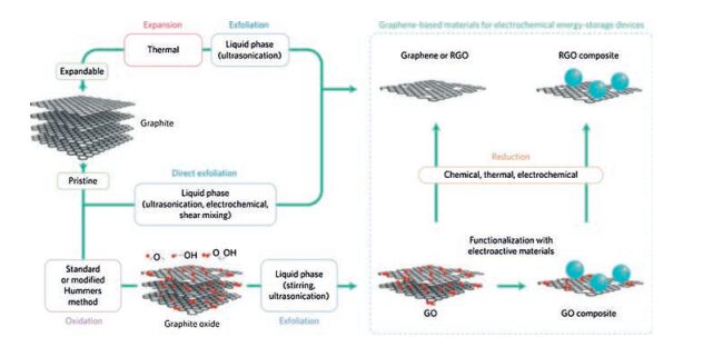
 下载:
下载:
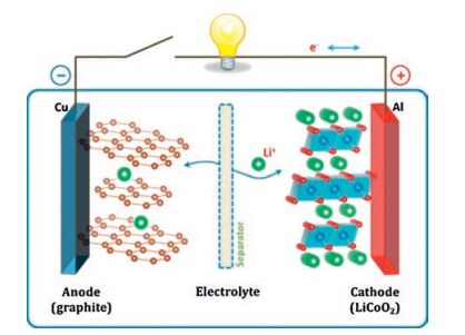
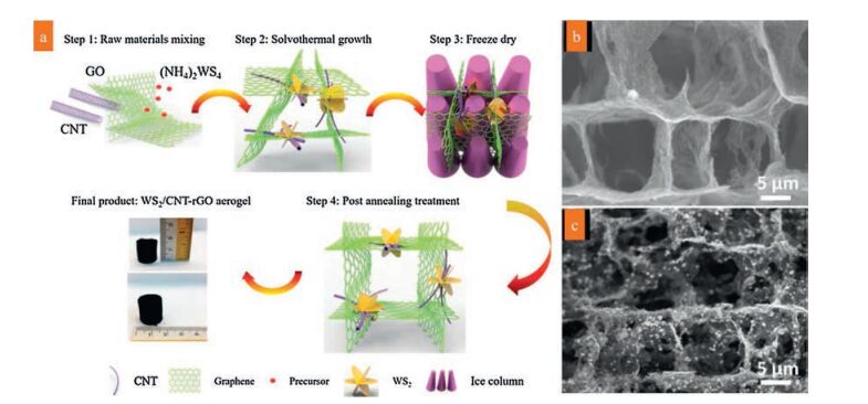
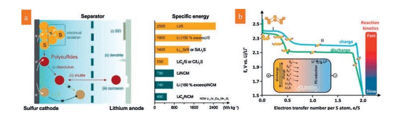
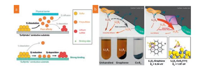
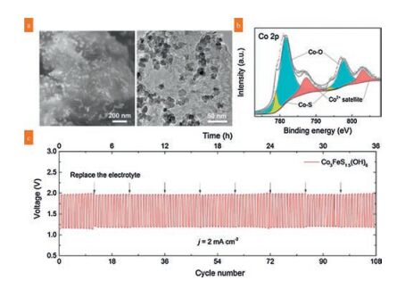
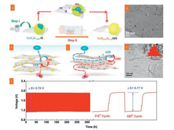
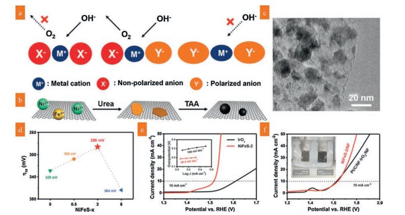
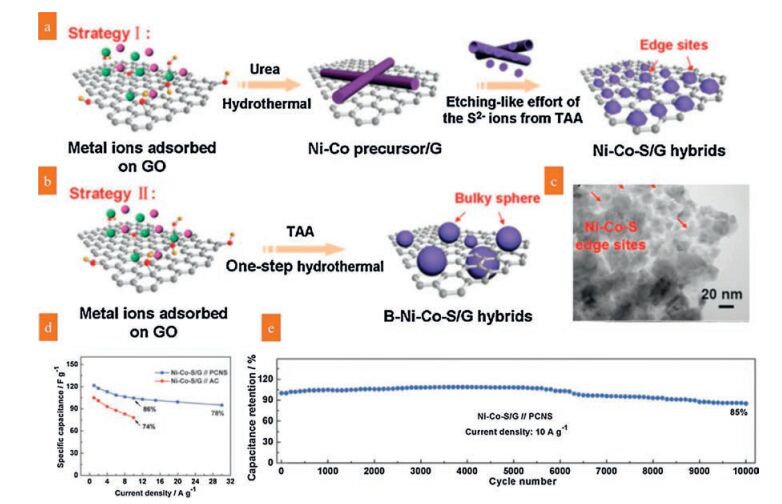
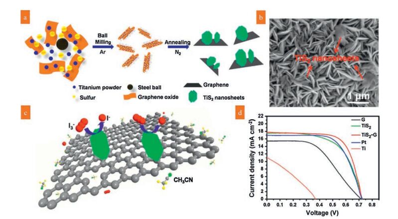
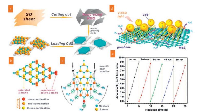
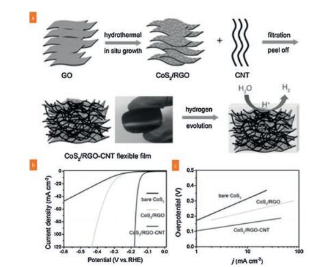

 下载:
下载:


 下载:
下载: