Citation:
Shen Shenghui, Deng Shengjue, Zhong Yu, Wu Jianbo, Wang Xiuli, Xia Xinhui, Tu Jiangping. Binder-free carbon fiber/TiNb2O7 composite electrode as superior high-rate anode for lithium ions batteries[J]. Chinese Chemical Letters,
2017, 28(12): 2219-2222.
doi:
10.1016/j.cclet.2017.11.031
Binder-free carbon fiber/TiNb2O7 composite electrode as superior high-rate anode for lithium ions batteries
State Key Laboratory of Silicon Materials, Key Laboratory of Advanced Materials and Applications for Batteries of Zhejiang Province, and School of Materials Science and Engineering, Zhejiang University, Hangzhou 310027, China
b.
Zhejiang Provincial Key Laboratory for Cutting Tools, Taizhou University, Taizhou 318000, China
Received Date:
29 October 2017 Accepted Date:
22 November 2017 Revised Date:
19 November 2017 Available Online:
22 December 2017
Abstract:
Construction of advanced high-rate anodes is critical for the development of high-power lithium ion batteries (LIBs). In this work, we report a binder-free carbon fiber (CF)/titanium niobium oxide (TiNb2O7 (TNO)) composite electrode via a simple solvothermal method combined with heat treatment. Continuous TNO film consisting of cross-linked TNO nanoparticles of 30-50 nm is strongly anchored on the carbon fiber forming integrated CF/TNO composite electrode. Owing to the intimate threedimensional structure, the as-prepared CF/TNO electrode presents exceptional high-rate performance (245 mAh/g at 1 C, and 138 mAh/g at 80 C) and enhanced cyclability with a capacity of 150 mAh/g at the current density of 10 C after 1000 cycles. Our results demonstrate the CF/TNO electrode as efficient anode for application in high-power lithium ion batteries.
The worsening environmental problems spur on us to developgreen energy storage devices [1].Particularly, lithium ion batteries(LIBs) have conquered the markets of electronics and electricvehicles without controversy and become the most popularbattery since 1990s [2-4].Though, as compared to supercapacitors, LIBs have the advantage of larger energy density, they suffer fromrelatively low power density [5-7].It is accepted that theperformance of LIBs is largely dependent on innovation/optimization of electrode materials [8].Currently, various alternative anodecandidates (such as graphite [9], Sn [8], Si [10], Li4Ti5O12 [11, 12] andtitanium niobium oxide (TNO) [13, 14]) have been the subject ofintense research.
Of these candidates, titanium niobium oxide (TiNb2O7, TNO)have attracted tremendous attentions due to the followingadvantages: 1) Relative high working voltage platform (1.6 V vs.Li/Li+) can hinder the formation of SEI layers.2) Large theoreticalcapacity of 388 mAh/g due to multi-redox couples (Nb4+/Nb5+, Nb3+/Nb4+ and Ti3+/Ti4+), higher than that of Li4Ti5O12 (175 mAh/g).3) High lithium ion diffusion coefficient owing to Wadsley-Rothshear structure of TiNb2O7 (Ti4+ and Nb5+ ions with molar ratios of 1:2 randomly occupy the octahedral sites connected by edges and corners and no cations are resided at the tetrahedral sites).However, the poor electron/ion transfer in bulk TNO limits itsfurther commercial application.As a result, appropriate steps mustbe taken to improve the electrochemical performance of TiNb2O7.To date, a variety of improved TNO electrodes have been reportedby doping or introducing conductive layers on TNO nanostructures.Liu et al.[15] synthesized Ag coated TiNb2O7 composites by a facilesolid-state reaction showing a capacity of 170 mAh/g at 30 C.Rudoped TiNb2O7 proposed by Lin et al.[16] obtained a capacity of 181 mAh/g after 100 cycles at 5 C with a capacity retention of 90.1%.TiNb2O7 hollow nanofiber prepared by Yu et al.[17] possessedsuperior electrochemical performance with a reversible capacity of158 mAh/g at a current density of 10 C after 900 cycles.TiNb2O7 nanoparticles synthesized by Li et al.[18] showed enhanced rateperformances with 175 mAh/g at 5 C and 138 mAh/g at 10 C, respectively.The above works are mainly focused on the TNOpowder electrode.The presence of insulating binders in thepowder electrode would undermine the electrochemical performance [19].Therefore, there is still huge room left to constructflexible and binder-free TNO electrodes [20-23].
In the present work, we construct a novel binder-free carbonfiber/titanium niobium oxide (CF/TNO) composite electrode via asimple solvothermal method combined with heat treatment.Benefiting from the smart three-dimensional structure and highly conductive carbon fibers, the as-prepared CF/TNO electrodepresents superior high-rate performance (245 mAh/g at 1 C, and 138 mAh/g at 80 C) and improved cyclability with a capacity of150 mAh/g at the current density of 10 C after 1000 cycles.Ourwork demonstrates the flexible and binder-free CF/TNO electrodeas efficient anode for high-power lithium ion batteries.
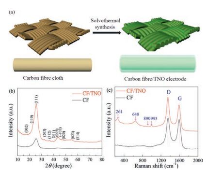
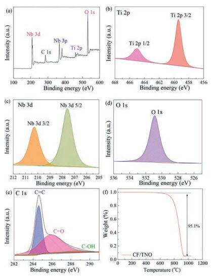
The fabrication schematics of CF/TNO electrode is shown in Fig.1a.The carbon fibre cloth is used as the substrate for thegrowth of TNO film via a facile hydrothermal method (detailedinformation see Supporting information).To check the structurein formation, phase evolution and elementary composition, X-raydiffraction (XRD), Raman spectra and XPS spectra are employed.Fig.1b shows the XRD patterns of CF and as-prepared CF/TNOcomposite electrode.The diffraction peaks at 23° and 43° in bothsamples are corresponding to (002) and (004) crystal planes ofgraphitic carbon (JCPDS No.65-6212) [24].Compared with the XRDpattern of CF, it can be clearly observed that the other strongdiffractions of CF/TNO are index well with TiNb2O7 phase (JCPDS No.77-1374).The above results are supported by Raman result.Asshown in Fig.1c, apart from the peaks of CF (1355 cm-1 and1590 cm-1 for D band and G band, respectively), new peaks appearat 993, 890, 648 and 261 cm-1, which belong to TiNb2O7 phase.XPSspectra (Fig.2a) proving the presence of Ti, Nb, O, C elements andtestify again the successful grown of TNO films on CF.According toTi 2p spectrum (Fig.2b), there are two peaks respectively located at465 eV and 459 eV with about 6 eV binding energy separation confirming the existence of Ti4+ [25].In Nb 3d spectra (Fig.2c), corelevels of Nb 3b 5/2 (210 eV) and Nb 3d 3/2 (207 eV) arecorresponding to the state of Nb5+.The high-resolution spectrumof O 1 s consists of one peak at 531 eV (Fig.2d), which demonstratesthe existence of O element in TNO phase and is related to thebinding energy of Nb/Ti-O.The C 1 s spectrum is resolved into threecomponents located at 284.6 eV, 286.2 eV and 288.6 eV (Fig.2e).The main peak at 284.6 eV is corresponding to the binding energyof C=C, and the other two small peaks can be indexed as theoxidative forms of hydrocarbons (COOH and C=O) [26].All resultsmutually support the formation of an integrated electrode withTNO film grown on carbon fiber substrates.To further calculatingthe weight content of TNO on carbon fibers, TG measurement isperformed with a temperature window of 20-1000 ℃ in air.Asshown in Fig.3f, the carbon fibers are oxidized to CO2 while TNO keeps intact.The proportion of TNO is calculated to be 4.9% with amass area of ~1 mg/cm2
图 1
图 1
(a) Schematic illustration of the formation of CF/TNO electrode; (b) XRDpatterns of pure CF and CF/TNO; (c) Raman spectra of pure CF and CF/TNO electrodes.
Figure 1.
(a) Schematic illustration of the formation of CF/TNO electrode; (b) XRDpatterns of pure CF and CF/TNO; (c) Raman spectra of pure CF and CF/TNO electrodes.
图 2
(a) XPS spectra of wide survey scan and (b) Ti 2p, (c) Nb 3d, (d) O 1s, and (e) C1s of the CF/TNO composite electrode; (f) TG curve of CF/TNO electrode.
Figure 2.
(a) XPS spectra of wide survey scan and (b) Ti 2p, (c) Nb 3d, (d) O 1s, and (e) C1s of the CF/TNO composite electrode; (f) TG curve of CF/TNO electrode.
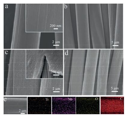
The microstructures and morphologies of bare CF and CF/TNO composite electrodes are shown in Figs.3a-d.Cross-linked carbonfibers with diameters of ~10 mm can be clearly seen in Figs.3a and b.After growth of TNO by the solvothermal method, the fiberarchitecture is well maintained, but the surface appearance ofcarbon fiber becomes much rougher.A layer of TNO film isuniformly coated on the carbon fibers (Fig.3c and d).According tothe profile image of TNO film, note that the thickness of the TNOfilm is ~150 nm.Moreover, energy dispersive spectrometer (EDS)elemental mapping images (Fig.3e) reveal the presence andhomogeneous distribution of Ti, Nb, O and C elements in CF/TNOelectrode, which is consistent with the result of XPS analysis.
图 3
图 3
SEM images of pure CF (a and b) and CF/TNO (c and d); (e) EDS elementalmapping images Ti, Nb, O and C in the CF/TNO composite electrode.
Figure 3.
SEM images of pure CF (a and b) and CF/TNO (c and d); (e) EDS elementalmapping images Ti, Nb, O and C in the CF/TNO composite electrode.
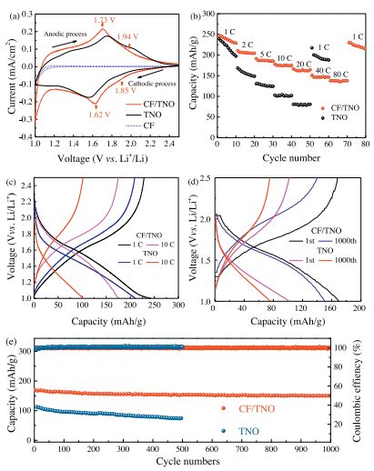
To evaluate the electrochemical performances of CF/TNOcomposite electrode, cyclic voltammogram (CV), rate performanceand cyclability tests are conducted.As shown in Fig.4a, CV curvesof pure CF, pure TNO and CF/TNO composites are performed at ascan rate of 0.2 mV/s in a voltage window of 1.0-2.5 V (vs.Li/Li+).Compared with pure TNO and CF/TNO, CF substrate does not showobvious redox peaks, suggesting that it provides little capacityduring the cyclic processes between 1.0-2.5 V.Thus, the capacity contribution of CF/TNO mainly depends on TNO.It can be seen thatthe CV curve of CF/TNO exhibit two main large sharp redox peaks at 1.73 V (anodic process) and 1.62 V (cathodic process), which areassigned to Nb5+/Nb4+ redox couple.It is worth noting that thereare another two relatively small peaks at 1.94 V/1.85 V based onthe reaction of Ti4+/Ti3+ and broad peaks at 1.0-1.4 V owing to the Nb4+/Nb3+ redox couple [27].Additionally, the electrochemical behavior of pure TNO is similar to the CF/TNO electrode.But incontrast, CF/TNO performs higher symmetrical CV curve, demonstrating the excellent reversibility of the redox reactions andcapacity retention.
图 4
图 4
(a) CV curves of the CF, TNO and CF/TNO electrode at a scan rate of 0.2 mV/s; (b) Rate performances of TNO and CF/TNO electrodes; (c) Discharge/charge voltageprofiles of the TNO and CF/TNO electrode at current densities of 1 C and 10 C; (d) The1st and 1000th discharge/charge voltage profiles of the TNO and CF/TNO electrodesat 10 C; (e) Cycling stability and Coulombic efficiency of TNO and CF/TNO electrodesat a current density of 10 C.
Figure 4.
(a) CV curves of the CF, TNO and CF/TNO electrode at a scan rate of 0.2 mV/s; (b) Rate performances of TNO and CF/TNO electrodes; (c) Discharge/charge voltageprofiles of the TNO and CF/TNO electrode at current densities of 1 C and 10 C; (d) The1st and 1000th discharge/charge voltage profiles of the TNO and CF/TNO electrodesat 10 C; (e) Cycling stability and Coulombic efficiency of TNO and CF/TNO electrodesat a current density of 10 C.
Fig.4b displays the rate performance of CF/TNO compositeselectrode at different discharge and charge rates varying from 1 C, 2 C, 5 C, 10 C, 20 C, 40 C to 80 C.The corresponding dischargecapacities are about 240, 205, 186, 175, 162, 146 and 137 mAh/g, respectively.The rate performance is superior to pure TiNb2O7 nanoparticles (synthesized as the same solvothermal condition), TiNb2O7 nanofibers [27], TiNb2O7 nanospheres [28], 3DOM TiNb2O7 (Table 1) [29].The related discharge/charge curves ofpure TNO and CF/TNO electrodes at 1C and 10C are demonstratedin Fig.4c.The curves exhibit two slopped regions, separatelyrelated to two different solid-solution reactions (Li0TiNb2O7 to Li0.8TiNb2O7, and from Li1.3TiNb2O7 to Li3.6TiNb2O7) [8].In addition, charge/discharge plateau (nearly 1.73 V/1.62 V at 1 C) exhibits inCF/TNO, while the pure TNO has a plateaus of 1.75 V/1.60 V, consistent with the CV redox peaks of Nb5+/Nb4+ above.In addition, the cyclability is also an important factor for high-powerapplications.It is noticeable that at the 1000th cycle, the chargeand discharge curves of CF/TNO electrode decay slightly, revealingits superior cycle stability (Fig.4d).After 1000 cycles at 10 C(Fig.4e), the discharge capacity of CF/TNO electrode decreasesfrom 170 mAh/g to 150 mAh/g with a capacity retention of 88%, better than the pure TNO based electrodes (decaying from 112 mAh/g to 72 mAh/g after 500 cycles).
表 1
表 1
Comparison of various TNO-based electrodes for LIBs.
Table 1.
Comparison of various TNO-based electrodes for LIBs.
According to the results stated above, it can be concluded thatthe CF/TNO composite electrode exhibits good electrochemical performances including rate performance and cyclability.Theunique intimate composite structure is responsible for theelectrochemical enhancement.The special three-dimensionalnetwork frame can provide a high specific surface area andincrease the active sites for reactions [7, 30-32].Simultaneously, the as-prepared CF/TNO composites are thin films rather thanpowders, which can operate without polymer binders resulting inreinforcement of electrochemical performances during charging/discharging processes [33].
In conclusion, we have synthesized carbon fibers supported TiNb2O7 composite electrode by a simple solvothermal methodfollowed by an annealing treatment.TNO films are uniformlygrown on the three-dimensional network and the average thickness is appropriate 150 nm.Benefiting from the smart threedimensional structure and highly conductive carbon fibers, the asprepared CF/TNO electrode shows excellent rate performance(245 mAh/g at 1 C, and 138 mAh/g at 80 C) and noticeable cyclability (150 mAh/g after 1000 cycles at the current densityof 10 C).Our research provides a simple strategy for construction ofbinder-free flexible anode material of lithium ion batteries.
Acknowledgments
This work is supported by National Natural Science Foundationof China (Nos.51502263 and 51772272), Qianjiang Talents Plan D(No.QJD1602029) and Startup Foundation for Hundred-TalentProgram of Zhejiang University.J.Tu acknowledges the support bythe Program for Innovative Research Team in University of Ministryof Education of China (No.IRT13037) and Key Science andTechnology Innovation Team of Zhejiang Province (No.2010R50013).
Figure 1
(a) Schematic illustration of the formation of CF/TNO electrode; (b) XRDpatterns of pure CF and CF/TNO; (c) Raman spectra of pure CF and CF/TNO electrodes.
Figure 2
(a) XPS spectra of wide survey scan and (b) Ti 2p, (c) Nb 3d, (d) O 1s, and (e) C1s of the CF/TNO composite electrode; (f) TG curve of CF/TNO electrode.
Figure 4
(a) CV curves of the CF, TNO and CF/TNO electrode at a scan rate of 0.2 mV/s; (b) Rate performances of TNO and CF/TNO electrodes; (c) Discharge/charge voltageprofiles of the TNO and CF/TNO electrode at current densities of 1 C and 10 C; (d) The1st and 1000th discharge/charge voltage profiles of the TNO and CF/TNO electrodesat 10 C; (e) Cycling stability and Coulombic efficiency of TNO and CF/TNO electrodesat a current density of 10 C.

 下载:
下载:


 下载:
下载:


 下载:
下载: