Citation:
Sun Yi, Liang Xin, Xiang Hongfa, Yu Yan. Free-standing vanadium pentoxide nanoribbon film as a high-performance cathode for rechargeable sodium batteries[J]. Chinese Chemical Letters,
2017, 28(12): 2251-2253.
doi:
10.1016/j.cclet.2017.11.028
Free-standing vanadium pentoxide nanoribbon film as a high-performance cathode for rechargeable sodium batteries
Anhui Provincial Key Laboratory of Advanced Functional Materials and Devices, School of Materials Science and Engineering, Hefei University of Technology, Hefei 230009, China
b.
Key Laboratory of Materials for Energy Conversion Chinese Academy of Sciences, Department of Materials Science and Engineering, University of Science and Technology of China, Hefei 230026, China
Received Date:
12 October 2017 Accepted Date:
20 November 2017 Revised Date:
15 November 2017 Available Online:
22 December 2017
Abstract:
Vanadium pentoxide (V2O5·nH2O) nanoribbons are synthesized via a hydrothermal process. These ribbons are 20 nm thick, 200 nm to 1 μm wide and several tens of micrometers long. Free-standing binder-free films are prepared by using these nanoribbons with multi-walled carbon nanotubes (MWCNTs) and used as the cathode for rechargeable sodium batteries. The large interlayer space between the V2O5 bilayers can enhance the kinetics of sodium ion intercalation/deintercalation. In addition, the intertwining network of the V2O5·0.34H2O film provides efficient electron conduction pathways and shortens diffusion distances of sodium ion. The electrochemical tests prove that the freestanding V2O5·0.34H2O film cathode delivers high reversible specific capacities (190 mAh/g) and good cycling stabilities (170 mAh/g after 150 cycles) in the voltage range between 1.5 V and 3.5 V.
In order to effectively utilize uncontinous renewable energy (e.g., solar and wind energy), advanced energy storage systems should be developed. Rechargeable sodium batteries, as an alternative energy storage system to lithium-ion batteries (LIBs), have world-widely attracted researchers' attentions benefiting from their potentially low cost and abundant supply of sodium sources [1-4]. However, the development of sodium batteries remains a challenge considering the lack of the high-performance electrode materials, especially the cathode materials due to either low sodium storage capacity (usually less than 160 mAh/g) or poor cycling ability [5-8]. The ionic radius of sodium ion is 55% larger than that of lithium ion, which requires a more open framework to enhance the kinetics of sodium ion intercalation/deintercalation reaction and maintain structural stability during cycling [9-11].
Vanadium pentoxide (V2O5) has been extensively studied for the potential applications in LIBs due to its low cost and high energy density [12-17], but relatively limited in rechargeable sodium batteries [18-20]. It is considered to be a promising cathode material due to the layered framework structure that allows facile ion intercalation/deintercalation and multiple redox reactions which deliver high specific capacities [16-18]. In addition, a particular type of vanadium pentoxide, which has larger interlayer space between well ordered stacking of V2O5 bilayers, is considered a more attractive cathode material for metal batteries [21]. Tepavcevic et al. have reported high reversible capacity and long lifetime of bilayered V2O5 in rechargeable sodium batteries, which presents the critical role of microstructure [22]. Nevertheless, the bulk V2O5 cathodes are still suffered from sluggish ion diffusion kinetics and low electrical conductivity. To overcome these drawbacks, various nanostructured V2O5 materials, such as hollow nanospheres [20], nanobelts [23] and amorphous films [24] have been investigated to develop highperformance electrodes for rechargeable sodium batteries.
Recently, the free-standing electrodes have been fabricated with improved performance for LIBs [25, 26]. Compared to conventional LIB electrodes, those free-standing electrodes without polymer binders, such as polyvinylidene fluorideare (PVDF), not only get the benefit of enhanced electrical conductivity, but also have great potential for high-temperature applications above 200 ℃, at which most conventional binders are instable. In addition, free of inactive materials (binders and collectors) also increase the overall energy density of the electrodes. As for rechargeable sodium batteries, Wang et al. have presented freestanding nitrogen-doped carbon nanofiber films anode by electrospinning [27]. David et al. have reported MoS2/graphene composite paper anode by vacuum filtration [28]. However, the free-standing cathode for rechargeable sodium batteries has seldom been studied.
Herein, we fabricated V2O5·nH2O nanoribbons via a hydrothermal approach. These ribbons are further used to prepare a freestanding film with multi-walled carbon nanotubes (MWCNTs). The large interlayer space between the V2O5 bilayers can improve the kinetics of sodium ion intercalation/deintercalation. The intertwining network structure provides efficient electron conduction pathways and short sodium ion diffusion distances. The electrochemical tests reveal that the V2O5 free-standing film cathode delivers a high reversible specific capacities (190 mAh/g) and good cycling stabilities (170 mAh/g after 150 cycles) in the voltage range of 1.5-3.5 V.
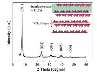
The X-ray diffraction pattern of the product obtained after the hydrothermal treatment is shown in Fig. 1. It displays a set of characteristic (00l) peaks for a layered V2O5·nH2O phase, which is in a good agreement with the standard pattern (JCPDS card No.40-1296). The V2O5 layers are perpendicular to the stacking axis, which is confirmed by no (hk0) and (hkl) reflections in the XRD pattern. The layer spacing of the hydrated V2O5 phase is calculated to be 11.6 Å from a strong diffraction peak at 2θ = 7.6°, which indicates the crystal structure consists of two-dimensional (2D) bilayered stacks separated by expanded interlayer spacing [22, 28]. The expanded spacing could be associated with the intercalation of water molecules [29, 30]. This crystal structure with expanded interlayer space can facilitate the diffusion of sodium ions.
图 1
图 1
XRD pattern of the V2O5·nH2O nanoribbons after hydrothermal process; inset: crystalline structure of V2O5·nH2O (water molecules not shown here).
Figure 1.
XRD pattern of the V2O5·nH2O nanoribbons after hydrothermal process; inset: crystalline structure of V2O5·nH2O (water molecules not shown here).
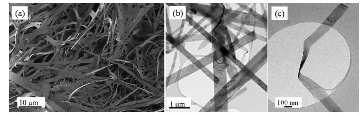
The morphology of the as-prepared sample was characterized by FESEM. As shown in Fig. 2a, a large number of nanoribbons with a width from 200 nm to 1 μm and a length up to several tens of micrometers can be observed. The TEM image confirms that the asprepared V2O5·nH2O nanostructures are nanoribbons with an aspect ratio above 100 (Fig. 2b). Noticing the width of nanoribbons determined through TEM image are smaller than those observed in the FESEM image, which attributes to the fact that the nanoribbons tend to grow together in the form of bundles. As some of the nanoribbons can be rolled up to expose their side views (Fig. 2b and c), the thickness of the nanoribbons is estimated to be about 20 nm, which also offers a short path for sodium ion diffusion in the crystal structure. In addition, these nanoribbons with high aspect ratio exhibit great mechanical flexibility and facilely entangle into meshes with an intertwining network (Fig. 2).
图 2
图 2
(a) SEM, and (b, c) TEM images of the V2O5·nH2O nanoribbons.
Figure 2.
(a) SEM, and (b, c) TEM images of the V2O5·nH2O nanoribbons.
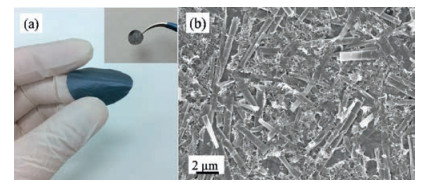
For rechargeable sodium battery applications, the free-standing V2O5 film cathode was fabricated by the intertwining nanoribbons with multi-walled carbon nanotubes (MWCNTs) (Fig. 3a and b). According to the elemental analysis, the weight percentage of C, H in the film is 20.49%, 0.29%, respectively. Based on these results, the chemical formula of the as-prepared sample can be determined to be V2O5·0.34H2O and weight percentage of the active materials in the cathode is 79.51%. Here, the MWCNTs not only provide fast electron transport pathways, but also improve the mechanically property of the free-standing film, even though their capacity contribution for sodium storage is negligible.
图 3
图 3
(a) Digital photograph of free-standing film by V2O5·0.34H2O nanoribbons and MWCNTs (inset: the digital photograph of the film electrode), (b) SEM image of the free-standing film.
Figure 3.
(a) Digital photograph of free-standing film by V2O5·0.34H2O nanoribbons and MWCNTs (inset: the digital photograph of the film electrode), (b) SEM image of the free-standing film.
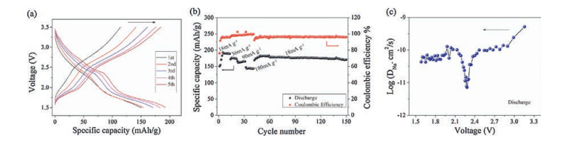
To study the sodium storage properties of this free-standing binder-free film cathode, the electrochemical performance was evaluated by galvanostatic charge–discharge. Fig. 4a shows the voltage profiles of the free-standing electrode for the first five cycles at a current density of 18 mA/g in a voltage range of 1.5-3.5 V (vs. Na+/Na). The discharge curves are all composed of two plateaus (around 2.4 V and 1.7 V), which should correspond to sodium-ion insertion into the lattice framework of V2O5·0.34H2O nanoribbons with two phase transitions [21, 22]. We suppose that sodium ions totally intercalate the interlayer space of V2O5 structure, and the reactions might happen as following:
图 4
图 4
(a) The voltage profiles of free-standing V2O5·0.34H2O film electrode at a current density of 18 mA/g, (b) rate and cycling performance of free-standing V2O5·0.34H2O film electrode, (c) chemical Na+ diffusion coefficient of the free-standing electrode during discharge process.
Figure 4.
(a) The voltage profiles of free-standing V2O5·0.34H2O film electrode at a current density of 18 mA/g, (b) rate and cycling performance of free-standing V2O5·0.34H2O film electrode, (c) chemical Na+ diffusion coefficient of the free-standing electrode during discharge process.
According to the Eqs. (1) and (2), the theoretical capacity of V2O5·0.34H2O can be calculated as 143 mAh/g(NaV2O5·0.34H2O)or 285 mAh/g (Na2V2O5·0.34H2O) for sodium ion intercalation/deintercalation process. The free-standing electrode delivers an initial discharge capacity of 150.3 mAh/g, with the subsequent charge capacity of 114.3 mAh/g. The high irreversible capacity loss can be resulted from the side reactions at the large surface area of the nanostructures. It should be noted that the discharge-charge profiles in the subsequent cycles are different from those of the first one, with more obviously voltage plateaus and increased capacities. It exhibits a discharge capacity of 192.5 mAh/g and a subsequent charge capacity of 185mAh/gat the fifth cycle.The charge/discharge profiles keep unchanged till 6-8 cycles and subsequent cycles are shown in Fig. S1 (Supporting information). This can be attributed to the electrolyte gradually diffusing into the nanovoids of the electrode and large spacing between bilayer stacks during the initial activation process [23].
Fig. 4b displays rate and cycling performances of the freestanding film cathode at various current densities from 18 to 180 mA/g. It delivers reversible capacities of 190, 174, 165 and 145 mAh/g at current densities of 18, 36, 90 and 180 mA/g, respectively. When the current returns to 18 mA/g, the capacity maintains around 180 mAh/g. Moreover, after the rate capability test, the free-standing cathode maintained a capacity of 170 mAh/g at 0.18 mA/g charge/discharge current density up to 150 cycles (Fig. 4b). The good performance of this film electrode can be ascribed to the unique crystal structure of V2O5·0.34H2O and interconnected conductive structure. The large interlayer space of V2O5·0.34H2O can enhance the kinetics of sodium ion intercalation/deintercalation, which is proved by galvanostatic intermittent titration technique (GITT) measurement (Fig. 4c, Figs. S2 and S3 in Supporting information). The sodium ion diffusion coefficients of the free-standing electrode are calculated between 5 ×10⁻¹⁰ cm2/s and 7 × 10-12 cm2/s, which are generally much higher than those reported previously [31]. The intertwining network of V2O5·0.34H2O ribbons with MWCNTs also provides efficient electron conduction pathways and shortens diffusion distances of sodium ion.
In summary, the V2O5·0.34H2O nanoribbons with large interlayer spacing between bilayered stacks are facilely synthesized by a hydrothermal process. A free-standing binder-free film is fabricated by using these nanoribbons with MWCNTs. Due to the unique crystal structure and intertwining conductive network, this cathode film delivers a high reversible specific capacity (190 mAh/g) and good cycling stability (170 mAh/g after 150 cycles). Such a composite film can be a potential binder-free cathode of rechargeable sodium batteries for desired energy storage applications.
Acknowledgments
This work was supported by the National Natural Science Foundation of China (Nos. 51372060, 21676067 and 21606065), Anhui Provincial Natural Science Foundation of China (No. 1708085QE98), the Fundamental Research Funds for the Central Universities and the Opening Project of CAS Key Laboratory of Materials for Energy Conversion (No. KF2016005).
Appendix A. Supplementary data
Supplementary data associated with this article can be found, in the online version, at doi: 10.1016/j.cclet.2017.11.028.
[1]
S.W. Kim, D.H. Seo, X.H. Ma, et al., Adv. Energy Mater. 2(2012) 710-721. doi: 10.1002/aenm.201200026
[2]
N. Yabuuchi, K. Kubota, M. Dahbi, et al., Chem. Rev. 114(2014) 11636-11682. doi: 10.1021/cr500192f
[3]
D. Kundu, E. Talaie, V. Duffort, et al., Angew. Chem. Int. Ed. 54(2015) 3431-3448. doi: 10.1002/anie.201410376
[4]
Y.M. Li, Y.S. Hu, M.M. Titirici, et al., Adv. Energy Mater. 6(2016) 1600659. doi: 10.1002/aenm.201600659
[5]
M. Sathiya, K. Hemalatha, K. Ramesha, et al., Chem. Mater. 24(2012) 1846-1853. doi: 10.1021/cm300466b
[6]
Y.J. Fang, L.F. Xiao, X.P. Ai, et al., Adv. Mater. 27(2015) 5895-5900. doi: 10.1002/adma.201502018
[7]
D.D. Yuan, W. He, F. Pei, et al., J. Mater. Chem. A 1(2013) 3895-3899. doi: 10.1039/c3ta01430d
Figure 1
XRD pattern of the V2O5·nH2O nanoribbons after hydrothermal process; inset: crystalline structure of V2O5·nH2O (water molecules not shown here).
Figure 3
(a) Digital photograph of free-standing film by V2O5·0.34H2O nanoribbons and MWCNTs (inset: the digital photograph of the film electrode), (b) SEM image of the free-standing film.
Figure 4
(a) The voltage profiles of free-standing V2O5·0.34H2O film electrode at a current density of 18 mA/g, (b) rate and cycling performance of free-standing V2O5·0.34H2O film electrode, (c) chemical Na+ diffusion coefficient of the free-standing electrode during discharge process.

 下载:
下载:


 下载:
下载:


 下载:
下载: