 Figure 2.
Effects of foaming temperature on cell morphology in terms of the average cell size and cell density
Figure 2.
Effects of foaming temperature on cell morphology in terms of the average cell size and cell density
Citation:
Jia Wang, Li Zhang, Jin-biao Bao. Supercritical CO2 Assisted Preparation of Open-cell Foams of Linear Low-density Polyethylene and Linear Low-density Polyethylene/Carbon Nanotube Composites[J]. Chinese Journal of Polymer Science,
2016, 34(7): 889-900.
doi:
10.1007/s10118-016-1806-4

Supercritical CO2 Assisted Preparation of Open-cell Foams of Linear Low-density Polyethylene and Linear Low-density Polyethylene/Carbon Nanotube Composites
English
Supercritical CO2 Assisted Preparation of Open-cell Foams of Linear Low-density Polyethylene and Linear Low-density Polyethylene/Carbon Nanotube Composites
Abstract:
The open-cell structure foams of linear low-density polyethylene (LLDPE) and linear low-density polyethylene (LLDPE)/multi-wall carbon nanotubes (MWCNTs) composites are prepared by using supercritical carbon dioxide (sc-CO2) as a foaming agent. The effects of processing parameters (foaming temperature, saturation pressure, and depressurization rate) and the addition of MWCNTs on the evolution of cell opening are studied systematically. For LLDPE foaming, the foaming temperature and saturation pressure are two key factors for preparing open-cell foams. An increase in temperature and pressure promotes both the cell wall thinning and cell rupture, because a high temperature results in a decrease in the viscosity of the polymer, and a high pressure leads to a larger amount of cell nucleation. Moreover, for the given temperature and pressure, the high pressurization rate results in a high pressure gradient, favoring cell rupture. For LLDPE/MWCNTs foaming, the addition of MWCNTs not only promotes the cell heterogeneous nucleation, but also prevents the cell collapse during cell opening, which is critical to achieve the open-cell structures with small cell size and high cell density.
-
Key words:
- Linear low-density polyethylene
- / MWCNTs
- / Supercritical carbon dioxide
- / Foam
- / Open-cell morphologies
-
INTRODUCTION
Foamed polymeric materials exhibit high impact strength, stiffness-to-weight ratio and a low thermal conductivity, compared with unfoamed polymers. They have been widely applied in automobile industry, food packaging and thermal insulation, as well as in controlled release system and membranes for liquid separations[1-11]. There are several methods to prepare polymeric foams, including gas foaming, thermally induced phase separation, emulsion freeze-drying, particulate leaching/solvent casting, and 3D printing technique[10-14]. Among them, gas foaming especially supercritical carbon dioxide (sc-CO2) foaming, is the most commonly and environmentally used method to prepare foamed polymeric materials[4, 10, 11, 14-17].
For polymeric foams, the cell structure can be classified into two categories: (1) open-cell structure, whose cells are interconnected with each other via microchannels; (2) closed-cell structure, which possesses isolated cells with continuous cell wall. For particular application such as bioscaffold, battery separators and separation membranes, open-cell structure is preferred. These applications require an ideal structure possessing highly interconnected pores to allow infiltration, and transportation. However, a conventional sc-CO2 foaming process often produces microcellular foams with closed cells. To create open-cell foams, cell walls between cells should be broken while cells maintain their distinctive cellular shapes without coalescence[18, 19]. For high open-cell content, the cell walls should be ruptured to a great extent, whereas cells may collapse during the cell rupture process. Therefore, it is still challenging to obtain foams with a high open-cell content using sc-CO2 as a foaming agent. Over the past decades, several strategies have been made to prepare open-cell foams, including optimization of processing parameters[20-27], use of a second blowing agent to induce secondary cell nucleation and growth[28-30], use of polymer blends with co-continuous morphologies[31-33], and blending of two polymers with hard and soft regions[34].
In summary, most of the above mentioned studies are focused on the preparation of porous materials and few of them are on the mechanism of cell opening. In a foaming process, as cells grow in size, conterminal cells gradually get close to each other, leading to the thinning even rupture of cell walls[18, 32, 34]. However, when cells rupture, they may coalescence, leading to larger and closed cells. Hence, cell growth, rupture and coalescence interact with each other during the foaming process.
Polyethylene (PE) foam is one of the most important plastic foams starting its commercial production since 1940[35]. However, the commercial PE foams are typically with closed cells, the cell size of 0.1-1 mm and the cell density less than 106 cm-3[36]. Multi-wall carbon nanotubes (MWCNTs) have considered to be an ideal filler to promote the cell nucleation during the foaming process of polymer/MWCNTs composites[37-39], while we found that the addition of MWCNTs during polymer foaming process not only promotes the cell nucleation, but also results in the formtation of hard regions, which may prevent the cell collapse during cell opening.
Compared with other olefin polymers, the cell walls of LLDPE can break up easily during cell growth because of the suitable melt strength under the foaming conditions[34]. In this work, we aim at using a sc-CO2 foaming process to prepare open-cell foams of linear low-density polyethylene (LLDPE) and LLDPE/MWCNTs composites. The emphasis is on the effects of processing parameters (foaming temperature, saturation pressure, and depressurization rate) and the addition of MWCNTs on the evolution of cell opening. We show how to optimize processing parameters to obtain open-cell structures with high open contents and tunable cell sizes.
EXPERIMENTAL
Characterization of Samples
The cell morphologies of foams were characterized using a TM3000 scanning electron microscope (SEM). Samples were immersed in liquid nitrogen for 3-5 min and then fractured. Before SEM observation, the samples were coated with gold in a vacuum chamber to make them conductive.
The cell morphologies were also characterized in terms of cell density and average cell size[42]. The cell size was obtained by analyzing SEM photographs using the software Image Pro-plus. The number of cells per unit volume (cm3) of a sample before foaming was determined from:
where n is the number of cells in the SEM micrograph, A the area of the micrograph (cm2) and Rv the ratio of the bulk density of the sample before foaming (ρp) to that of the one after foaming (ρf) using a balance equipped with a density measurement kit provided by Mettler Toledo. This method involved weighing specimen in air and water, respectively. When weighing a specimen in water, a net-like metal cover was used to immerse it in water. According to ASTM 792-00, the mass densities of foamed LLDPE, ρf, were calculated by:
where a is the apparent mass of specimen in air, w the apparent mass of the totally immersed net-like metal cover in water and b the apparent mass of the specimen and cover completely immersed in water. The volume expansion ratio of the foamed LLDPE, φ, is defined as the ratio of the bulk density of the unfoamed LLDPE (ρp) to that of the foamed one (ρf):
Finally, the average cell wall thickness (d) was calculated based on a cube model. It can be related to the expansion ratio (ϕ) and cell density (N0) according to the following equation[32].
Foaming Process
An autoclave foaming system was constructed and used for CO2 foaming[41]. The LLDPE and LLDPE/MWCNTs sheets were saturated with CO2 under prescribed pressure and temperature for 2 h to reach the saturation equilibrium. Thereafter, the gas was rapidly released to the ambient pressure to induce cell nucleation. Then foamed samples were quickly taken out of the autoclave for subsequent analyses. The maximum value of the depressurization rate was denoted as the depressurization rate of the foaming process.
Materials
LLDPE (HES-1003 NT7) pellets were purchased from Dow Chemical Company. Its MFI was 2.5 g/10min (190℃, 2.16 kg) and its melting temperature was 122℃. The raw multiwall carbon nanotubes (MWCNTs) have the diameter of about 8-15 nm, average length of about 10-30μm and the purity of larger than 95%. The raw MWCNTs were functionalized with octadecyl-amine according to the method provided by Qin et al.[40]. CO2 with a purity of 99.95 % was supplied by Fangxin Gas Inc, Ningbo.
Different weight percentages of MWCNTs were dispersed in LLDPE by a HaakeMiniLab (Thermo Electron, Germany) at the temperature of 190℃for 10 min at the rate of 50 r/min. The nanocomposites were then pressed into a sheet with a 2 mm thickness by the HaakeMiniJet (Thermo Electron, Germany) equipped with an instrumented mold. The cylinder temperature and mould temperature were 190℃and 60℃, respectively. The injection pressure was controlled at 50 MPa and the injection time was 3 s. The post pressure and holding time were 45 MPa and 6 s, respectively.
RESULTS AND DISCUSSION
Effects of Foaming Temperature
Figure 1 shows the evolution of cell morphology of the LLDPE foamed at 28 MPa saturation pressure over a relatively wide range of foaming temperature (124-140℃). At 124℃, small holes are formed on cell walls (see white circles in Fig. 1b), indicating that cell walls begin to rupture at this temperature. More small holes are seen at a higher temperature (see Fig. 1c). When the temperature is at 130℃(see Fig. 1d), open-cell structures with“platelet-like”cell walls are obtained. Nevertheless, there is still a small number of small holes on cell walls (see white circles in Fig. 1d). A further increase in temperature to 134-136℃leads to perfect“platelet-like”open-cell structures (Figs. 1e-1f) with a small number of“rod-like”cell walls (see white circles in Fig. 1f). When the temperature is increased to above 140℃, open-cell structures with“rod-like”cell walls are obtained (Figs. 1g-1h).
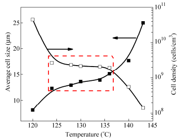
Figure 2 shows that the average cell size increases with increasing foaming temperature whereas the cell density decreases accordingly. However, it should be noted that the average cell size and cell density do not vary much in the range of 124℃to 136℃(see the dotted rectangle in Fig. 2), which corresponds to cell opening in Fig. 1.
Figure 2.
Effects of foaming temperature on cell morphology in terms of the average cell size and cell density
It is well-known that cell growth and collapse occur simultaneously during a foaming process[44, 45]. Since not all cells are nucleated at the same time nor grow at the same speed, cells are non-uniform in size[42]. Therefore, during the cell growth process, neighboring small cells tend to collapse into larger ones to reduce the total gas-polymer interfacial energy. Consequently the cell collapse increases the cell size and decreases the cell density. However, when neighboring cells are interconnected with small holes on the cell walls or with“platelet-like”cell walls, the force leading to cell collapse gets weak. That is why the increase in the cell size and the decrease in the cell density become unobvious when the open-cell structure changes from“small holes”cell walls to“platelet-like”ones. On the other hand, if cell walls are too weak, as it can be the case for“rod-like”cell walls, cells may easily collapse during the cell growth, just like the situation shown in Fig. 1(g). When the foaming temperature is further increased to 140℃, the cell density sharply decreases and the average cell size rapidly increases.
Effects of Depressurization Rate
For given saturation pressure and foaming temperature, a higher depressurization rate generates a higher cell nucleation rate. Figure 5 shows the cell morphologies of LLDPE foams obtained at 28 MPa, 130 (or 136℃), and various depressurization rates. Cell structures are closed when the depressurization rate is 10 MPa/s, even if the foaming temperature and pressure are 136℃and 28 MPa, respectively (Figs. 5a and 5d). When the depressurization rate is increased to 100 MPa/s, open-cell structures are formed (Figs. 5b and 5e). When it is further increased to 300 MPa/s, open-cell structures are of even better quality (Figs. 5c and 5f). These results indicate that for given foaming temperature and pressure, the depressurization rate is also a very important parameter for preparing open-cell structures.
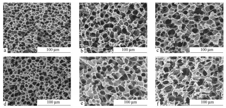 Figure 5.
Effect of depressurization rate on cell morphology of LLDPE foams obtained at 28 MPa, 130 (or 136℃): (a) 130℃, 10 MPa/s; (b) 130℃, 100 MPa/s; (c) 130℃, 300 MPa/s; (d) 136℃, 10 MPa/s; (e) 136℃, 100 MPa/s; (f) 136℃, 300 MPa/s
Figure 5.
Effect of depressurization rate on cell morphology of LLDPE foams obtained at 28 MPa, 130 (or 136℃): (a) 130℃, 10 MPa/s; (b) 130℃, 100 MPa/s; (c) 130℃, 300 MPa/s; (d) 136℃, 10 MPa/s; (e) 136℃, 100 MPa/s; (f) 136℃, 300 MPa/s
From Fig. 6, both the cell density and the average cell size increase with increasing depressurization rate, while the result of the increase in average cell size is not in line with the result reported in the literature[48]. At higher depressurization rates, cell walls got much thinner and many cells started to rupture and collapse subsequently, leading to obvious increase of the average cell size. Therefore, for preparing better open-cell structure (sharp increase of the cell density with unobvious increase of the average cell size), it is very important to prevent cells from collapsing while favoring cell wall rupture. Based on this principle, it is speculated that addition of solid particles like MWCNTs would favor the formation of open-cell morphologies. This will be discussed in next section.
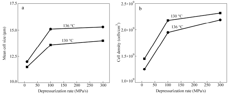 Figure 6.
Effects of the depressurization rate on cell morphology in terms of (a) the average cell size and (b) cell density
Figure 6.
Effects of the depressurization rate on cell morphology in terms of (a) the average cell size and (b) cell density
Figure 7 proposes a mechanism for the cell opening during a foaming process. Basically, cell opening proceeds in the following manner: (1) cell wall thinning as cells grow in size, and (2) wall opening of conterminal cells without cell coalescence. At the initial stage of foaming, conterminal cells gradually get close to each other as they grow in size. Cell walls get thinner and thinner and may start to rupture to form small holes in the cell walls. With the increase of foaming temperature and saturation pressure, the viscosity of the polymer decreases and the number of cell nucleation increases. Cell rupture becomes easier and two typical open-cell structures are formed:“platelet-like”cell walls and“rod-like”ones, and the latter have a higher cell open content than the former. During the cell opening process the cell rupture and cell collapse always occur simultaneously.“Platelet-like”cell walls are too weak to support cells. As cells further grow in size, they are prone to form“rod-like”structure or break up and collapse into large open-cells structure.
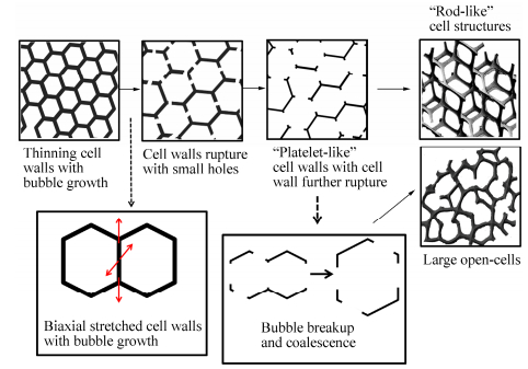 Figure 7.
Schematic of the evolution of cell opening during CO2 foaming process
Figure 7.
Schematic of the evolution of cell opening during CO2 foaming process
Figure 8 shows qualitative foaming windows for the formation of various types of cell structures at the depressurization rate of 300 MPa/s. Closed cell structures are formed when the foaming temperature is slightly above the melting temperature of the polymer (zone A in Fig. 8). As the temperature and pressure increase, cells start to rupture upon forming small holes on cell walls (zone B in Fig. 8). Cells further rupture and“platelet-like”open-cell structures are formed with a further increase in temperature and pressure (zone C in Fig. 8). Finally, the“rod-like”open-cell structures are formed when temperature and pressure are high enough (zone D in Fig. 8). One also notices that for a given temperature, a higher pressure leads to better open-cell structures.
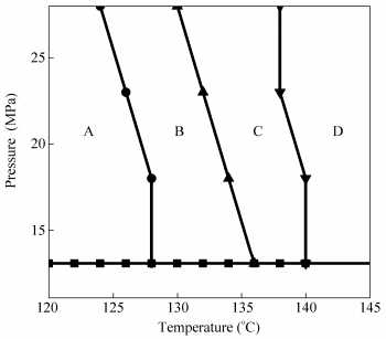 Figure 8.
Qualitative foaming windows for the formation of various cell structures: (zone A) closed cells; (zone B) open-cell with small holes in cell walls; (zone C)“platelet-like”open-cell structures; (zone D)“rod-like”open-cell structures
Figure 8.
Qualitative foaming windows for the formation of various cell structures: (zone A) closed cells; (zone B) open-cell with small holes in cell walls; (zone C)“platelet-like”open-cell structures; (zone D)“rod-like”open-cell structures
Preparation of Open-cell Structures of LLDPE/MWCNTs Foams
As we stated above, the open-cell structures can be achieved with high temperature and high CO2 saturation pressure. However, the cell walls may start to rupture and may subsequently collapse during cell growth with foaming temperature increasing. Therefore, for the preparation of open-cell structures, it is very important to prevent cells from collapsing while favoring cell wall rupture. Based on this principle, MWCNTs are introduced into the LLDPE matrix to favor the formation of open-cell morphologies. Figure 9 shows the cell morphologies of LLDPE and LLDPE/MWCNTs samples foamed at 28 MPa saturation pressure and various foaming temperatures. Figure 10 shows the effects of foaming temperature on cell morphology in terms of the average cell size and cell density. With foaming temperature increasing, the average cell size increases and the cell density decreases. Comparing the LLDPE foams with LLDPE/MWCNTs nanocomposite foams, one can see that the average cell size decreases and the cell density increases with the addition of MWCNTs at the same foaming temperature. This is because that the existing of MWCNTs in LLDPE matrix results in the heterogeneous nucleation[35]. It should be noted that the average cell size and cell density of LLDPE/MWCNTs nanocomposites foams do not vary much with temperature above 132℃. Especially at the temperature of 143℃, the average cell size of LLDPE/MWCNTs nanocomposite foams is obviously smaller than that of LLDPE foams, and the cell density of LLDPE/MWCNTs nanocomposite foams is far higher than that of LLDPE foams. It indicates that the existing of MWCNTs in cell walls may prevent the cell collapse during cell growth, leading to the small cell size and high cell density. In conclusion, with the addtion of MWCNTs, the complete open-cell structures are achieved with small cell size and high cell density.
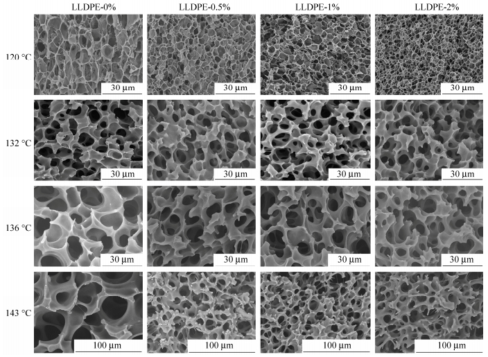 Figure 9.
Cell morphologies of LLDPE and LLDPE/MWCNTs samples foamed at 28 MPa saturation pressure and various foaming temperatures
Figure 9.
Cell morphologies of LLDPE and LLDPE/MWCNTs samples foamed at 28 MPa saturation pressure and various foaming temperatures
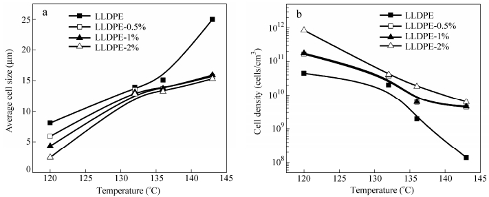 Figure 10.
Effects of foaming temperature on cell morphology in terms of (a) the average cell size and (b) cell density
Figure 10.
Effects of foaming temperature on cell morphology in terms of (a) the average cell size and (b) cell density
The LLDPE/MWCNTs nanocomposite foams with 2 wt% MWCNTs (LLDPE-2 wt%) are employed to investigate the effect of foaming pressure and temperature on cell morphologies. Figure 11 shows the cell morphologies of LLDPE-2 wt% samples foamed at various saturation pressures and foaming temperatures. Figure 12 shows the effects of foaming temperature on cell morphology in terms of the average cell size and cell density. For a certain temperature, the average cell size decreases and the cell density increases with foaming pressure increasing. On the other hand, for a certain foaming pressure, the average cell size increases and the cell density decreases with foaming temperature increasing. Nevertheless, the trend of the increase of average cell size and the decrease of cell density becomes weak with the temperature increasing when the temperature is above 130℃(see the dotted rectangles in Fig. 12).
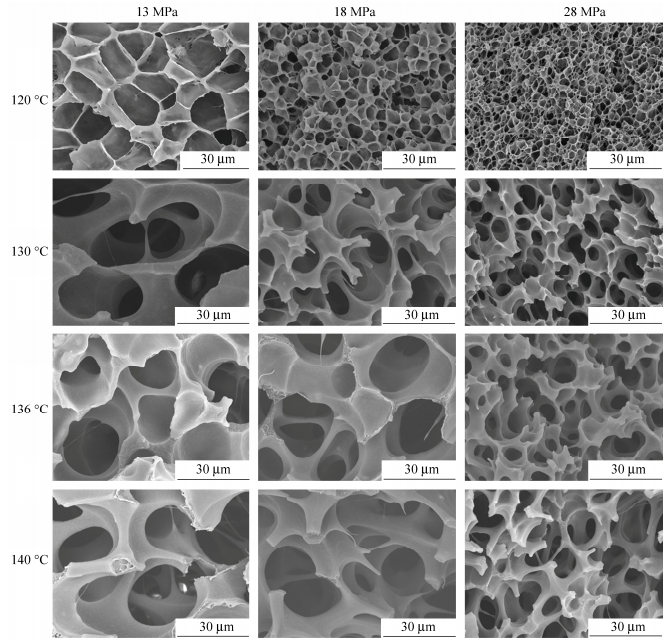 Figure 11.
Cell morphologies of LLDPE-2% samples foamed at various saturation pressures and foaming temperatures
Figure 11.
Cell morphologies of LLDPE-2% samples foamed at various saturation pressures and foaming temperatures
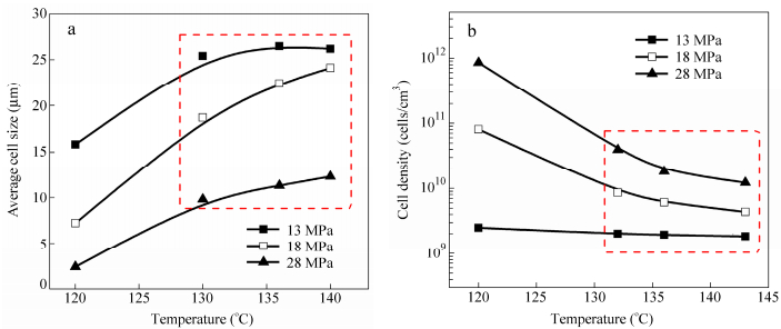 Figure 12.
Effects of foaming temperature on cell morphology in terms of (a) the average cell size and (b) cell density
Figure 12.
Effects of foaming temperature on cell morphology in terms of (a) the average cell size and (b) cell density
When the foaming temperature is lower than the melting temperature of LLDPE (122℃, measured by DSC), the close-cell structures are achieved. The cell size of LLDPE/MWCNTs nanocomposite foams is smaller than that of LLDPE foams, and the cell density of LLDPE/MWCNTs nanocomposite foams is higher than that of LLDPE foams, as the addition of MWCNTs promotes the heterogeneous nucleation. Although the heterogeneous nucleation mechanism is still under investigation, the addition of MWCNTs can reduce the nucleation free energy, and the uniform dispersion of MWCNTs can facilitate the formation of nucleation centers for a gaseous phase, which is similar with the reported results[27]. With foaming temperature increases (higher than the melting temperature of LLDPE), the cell walls start to rupture and the open-cell structures are achieved. As the foaming temperature further increases, the cells of LLDPE foams may easily collapse into large cells. On the other hand, the LLDPE/MWCNTs nanocomposite foams are prone to get the“rod-like”open-cell structures with small cell size. To be more specific, for the foaming of LLDPE/MWCNTs nanocomposites, the small cell size and high cell density are achieved, which results from the cell heterogeneous nucleation induced by MWCNTs. Moreover, the existing of MWCNTs in cell walls prevents the cell collapse during the cell opening.
Effects of Saturation Pressure
Figure 3 shows the cell morphologies of LLDPE foams obtained at 130℃(or 136℃) with various saturation pressures (the depressurization rate is kept constant at 100 MPa/s). For a given temperature, the cell size decreases with increasing pressure. Figure 4(a) shows that the average cell size decreases with increasing saturation pressure, while the cell density increases. It is well-known that, for a given temperature, the solubility of CO2 in polymers increases with increasing pressure[46, 47]. Therefore, cell walls will become thinner and will be more prone to rupture. Moreover, a higher pressure will lead to a larger number of cells. This is further confirmed by Fig. 4(b) which shows that the average cell wall thickness decreases with increasing pressure.
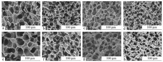 Figure 3.
Effects of saturation pressure on the cell morphology of LLDPE foams obtained at 130 or 136℃: (a) 130℃, 13 MPa; (b) 130℃, 18 MPa; (c) 130℃, 23 MPa; (d) 130℃, 28 MPa; (e) 136℃, 13 MPa; (f) 136℃, 18 MPa; (g) 136℃, 23 MPa; (f) 136℃, 28 MPa
Figure 3.
Effects of saturation pressure on the cell morphology of LLDPE foams obtained at 130 or 136℃: (a) 130℃, 13 MPa; (b) 130℃, 18 MPa; (c) 130℃, 23 MPa; (d) 130℃, 28 MPa; (e) 136℃, 13 MPa; (f) 136℃, 18 MPa; (g) 136℃, 23 MPa; (f) 136℃, 28 MPa
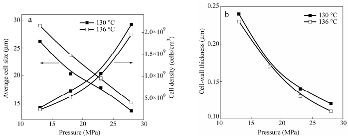 Figure 4.
Effects of saturation pressure on cell morphology in terms of (a) the average cell size and cell density and (b) average cell wall thickness
Figure 4.
Effects of saturation pressure on cell morphology in terms of (a) the average cell size and cell density and (b) average cell wall thickness
Preparation of Open-cell Structures of LLDPE Foam
In this work, the effects of foaming temperature, saturation pressure and depressurization rate on the cell morphologies are studied systemically. Table 1 shows the foaming conditions. Figure 1 shows the cell morphologies of the LLDPE foams obtained at the saturation pressure of 28 MPa and various foaming temperatures (120-143℃). As the temperature increases, the cell size increases and the cell structure changes from closed cells (Figs. 1a-1b) toward open ones (Figs. 1d-1h). This is because an increase in temperature brings about a decrease in viscosity of the polymer and consequently a decrease in the force that resists to the cell growth[43]. Cell walls get thinner and thinner and become prone to rupture. In addition, two types of open-cell walls can be observed: (a)“platelet-like”(Figs. 1d-1e) and (b)“rod-like”(Figs. 1f-1h). In what follows, we will study the effects of processing parameters (foaming temperature, saturation pressure and depressurization rate) on cell opening during the foaming process.
 Table 1.
Foaming conditions in this work
Table 1.
Foaming conditions in this work
Saturation temperature (℃) Saturation pressure (MPa) Depressurization rate (MPa/s) 120 13, 18, 23, 28 100 122 13, 18, 23, 28 100 124 13, 18, 23, 28 100 126 13, 18, 23, 28 100 128 13, 18, 23, 28 100 130 28 10 13, 18, 23, 28 100 28 300 132 13, 18, 23, 28 100 134 13, 18, 23, 28 100 136 28 10 13, 18, 23, 28 100 28 300 138 13, 18, 23, 28 100 140 13, 18, 23, 28 100 143 13, 18, 23, 28 100 Table 1. Foaming conditions in this work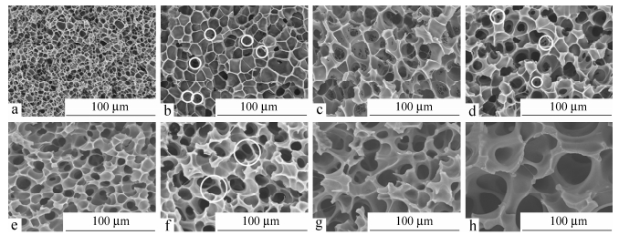 Figure 1.
Cell morphologies of LLDPE samples foamed at 28 MPa saturation pressure and various foaming temperatures: (a) 120℃; (b) 124℃; (c) 128℃; (d) 130℃; (e) 134℃; (f) 136℃; (g) 140℃; (h) 143℃
Figure 1.
Cell morphologies of LLDPE samples foamed at 28 MPa saturation pressure and various foaming temperatures: (a) 120℃; (b) 124℃; (c) 128℃; (d) 130℃; (e) 134℃; (f) 136℃; (g) 140℃; (h) 143℃
CONCLUSIONS
The open-cell structure foams of linear low-density polyethylene (LLDPE) and linear low-density polyethylene (LLDPE)/multi-wall carbon nanotubes (MWCNTs) composites were prepared by using sc-CO2, and the effects of foaming parameters and the addition of MWCNTs on the open-cell morphology were studied systematically. Cell walls start to rupture when the foaming temperature is above the melting temperature of the polymer. Three types of cell-open structures are possible: a) open-cell walls with small holes, b)“platelet-like”cell walls, and c)“rod-like”cell walls. The foaming temperature and saturation pressure are two key factors for controlling open-cell structures. A high temperature results in lowering of the viscosity of the polymer; and a high pressure favors large amount of cell nucleation and growth, resulting in cell wall thinning and cell rupture. Moreover, for given foaming temperature and pressure, the depressurization rate is a very important parameter. A high depressurization rate favors cell nucleation and growth, and cell rupture, on the other hand. Finally, the LLDPE/MWCNTs nanocomposite foams have the smaller cell size and higher cell density than the LLDPE foams. This is because that the addition of MWCNTs results in the cell heterogeneous nucleation, and also prevents the cell collapse during cell opening.
-
-
[1]
Arora, P. and Zhang, Z., Chem. Rev., 2004, 104: 4419
-
[2]
Rezwan, K., Chen, Q., Blaker, J. and Boccaccini, A.R., Biomaterials, 2006, 27: 3413
-
[3]
Wang, J., Lessard, B.H., Maric, M. and Favis, B.D., Polymer, 2014, 55: 3461
-
[4]
Pintado-Sierra, M., Delgado, L., Aranaz, I., Marcos-Fernández, Á., Reinecke, H., Gallardo, A., Zeugolis, D. and Elvira, C., J. Supercrit. Fluid, 2014, 95: 273
-
[5]
Huang, Q., Seibig, B. and Paul, D., J. Membr. Sci., 1999, 161: 287
-
[6]
Pientka, Z., Nemestóthy, N. and Bélafi-Bakó, K., Desalination, 2009, 241: 106
-
[7]
Shi, J.L., Li, H., Fang, L.F., Liang, Z.Y. and Zhu, B.K., Chinese J. Polym. Sci., 2013, 31(2): 309
-
[8]
Martina, M. and Hutmacher, D.W., Polym. Int., 2007, 56: 145
-
[9]
Annabi, N., Fathi, A., Mithieux, S.M., Weiss, A.S. and Dehghani, F., J. Supercrit. Fluid, 2011, 59: 157
-
[10]
Salerno, A., Zeppetelli, S., Di Maio, E., Iannace, S. and Netti, P., J. Supercrit. Fluid., 2012, 67: 114
-
[11]
Velasco, D., Benito, L., Fernández-Gutiérrez, M., San Román, J. and Elvira, C., J. Supercrit. Fluid, 2010, 54: 335
-
[12]
O'Brien, F.J., harley, B.A., Yannas, I.V. and Gibson, L., Biomaterials, 2004, 25: 1077
-
[13]
Nam, Y.S. and Park, T.G., Biomaterials, 1999, 20: 1783
-
[14]
Barry, J.A., Silva, M.C.G. and Gartmell, S., J. Mater. Sci., 2006, 41: 4197
-
[15]
Zhang, C., Zhu, B. and Lee, L.J., Polymer, 2011, 52: 1847
-
[16]
Tomasko, D.L., Li, H., Liu, D., Han, X., Wingert, M.J., Lee, L.J. and Koelling, K.W., Ind. Eng. Chem. Res., 2003, 42: 6431
-
[17]
Liao, X., and Nawaby, A.V., Ind. Eng. Chem. Res., 2012, 51: 6722
-
[18]
Enayati, M., Famili, M.H.N. and Janani, H., Iran Polym. J., 2013, 22: 417
-
[19]
Rodeheaver, B. and Colton, J., Polym. Eng. Sci., 2001, 41: 380
-
[20]
Serry Ahmed, M., Park, C. and Atalla, N., Cell. Polym., 2006, 25: 277
-
[21]
Keshtkar, M., Nofar, M., Park, C. and Carreau, P., Polymer, 2014, 55: 4077
-
[22]
Salerno, A., Di Maio, E., Iannace, S. and Netti, P., J. Supercrit. Fluid, 2011, 58: 158
-
[23]
Ruiz, J.A.R., Pedros, M., Tallon, J.M. and Dumon, M., J. Supercrit. Fluid, 2011, 58: 168
-
[24]
Markocčicč, E., Škerget, M. and Knez, Z.e., Ind. Eng. Chem. Res., 2013, 52: 15594
-
[25]
Jahani, D., Ameli, A., Jung, P.U., Barzegari, M.R., Park, C.B. and Naguib, H., Mater. Design., 2014, 53: 20
-
[26]
Wu, H.B., Haugen, H.J. and Wintermantel, E., J. Cell. Plast., 2011, 48: 141
-
[27]
Lee, L.J., Zeng, C., Cao, X., Han, X., Shen, J. and Xu, G., Compos. Sci. Technol., 2005, 65: 2344
-
[28]
Krause, B., Boerrigter, M.E., Van der Vegt, N.F.A., Strathmann, H. and Wessling, M., J. Membr. Sci., 2001, 187: 181
-
[29]
Lee, P.C., Naguib, H.E., Park, C.B. and Wang, J., Polym. Eng. Sci., 2005, 45: 1445
-
[30]
Gong, P., Taniguchi, T. and Ohshima, M., J. Mater. Sci., 2014, 49: 2605
-
[31]
Kohlhoff, D. and Ohshima, M., Macromol. Mater. Eng., 2011, 296: 770
-
[32]
Park, C.B., Padareva, V., Lee, P.C. and Naguib, H.E., J. Polym. Eng., 2005, 25: 239
-
[33]
Jiang, X.L., Liu, T., Zhao, L., Xu, Z.M. and Yuan, W.K., J. Cell. Plast., 2009, 45: 225
-
[34]
Lee, P.C., Wang, J. and Park, C.B., Ind. Eng. Chem. Res., 2006, 45: 175
-
[35]
Zhang, Y., Rodrigue, D. and Abdellatif, A.K., J. Appl. Polym. Sci., 2003, 90: 2111
-
[36]
Williams, J.M. and Wrobleski, D.A., J. Mater. Sci., 1989, 24: 4026
-
[37]
Zeng, C., Hossieny, N., Zhang, C. and Wang, B., Polymer, 2010, 51: 655
-
[38]
Tran, M.P., Detrembleur, C., Alexandre, M., Jerome, C. and Thomassin, J.M., Polymer, 2013, 54: 3261
-
[39]
Ameli, A., Nofar, M., Park, C.B., Pötschke, P. and Rizvi, G., Carbon, 2014, 71: 206
-
[40]
Qin, Y., Liu, L., Shi, J., Wu, W., Zhang, J., Guo, Z.X., Li, Y. and Zhu, D., Chem. Mater., 2003, 15: 3256
-
[41]
Bao, J.B., Liu, T., Zhao, L., Hu, G.H., Miao, X. and Li, X., Polymer, 2012, 53: 5982
-
[42]
Lee, P.C., Li, G., Lee, J.W.S. and Park, C.B., J. Cell. Plast., 2007, 43: 431
-
[43]
Bao, J.B., Liu, T., Zhao, L. and Hu, G.H., J. Supercrit. Fluid, 2011, 55: 1104
-
[44]
Leung, S.N., Park, C.B., Xu, D., Li, H. and Fenton, R.G., Ind. Eng. Chem. Res., 2006, 45: 7823
-
[45]
Guo, Q., Wang, J., Park, C.B. and Ohshima, M., Ind. Eng. Chem. Res., 2006, 45: 6153
-
[46]
Sato, Y., Takikawa, T., Takishima, S. and Masuoka, H., J. Supercrit. Fluid, 2001, 19: 187
-
[47]
Sato, Y., Fujiwara, K., Takikawa, T., Takishima, S. and Masuoka, H., Fluid Phase Equilib., 1999, 162: 261
-
[48]
Xu, Z.M., Jiang, X.L., Liu, T., Hu, G.H., Zhao, L., Zhu, Z.N. and Yuan, W.K., J. Supercrit. Fluid, 2007, 41: 299
-
[1]
-

 扫一扫看文章
计量
- PDF下载量: 0
- 文章访问数: 1787
- HTML全文浏览量: 39
 下载:
下载: